Internal shutter mechanism for a ganged fiber optic adapter

Inactive Publication Date: 2015-08-27
COMMSCOPE INC
View PDF2 Cites 10 Cited by
  • Summary
  • Abstract
  • Description
  • Claims
  • Application Information

AI Technical Summary

Benefits of technology

The present invention is about a shutter assembly that can be used in a data connector. This shutter assembly has shutters that can be opened and closed by inserting and removing a connector plug. Compared to existing solutions, this shutter assembly eliminates the need for manual opening and closing of the shutters. As a result, the user only needs to plug in the connector to open the shutter and remove the connector to close the shutter. This simplifies the process and makes the use of the data connector more convenient.

Problems solved by technology

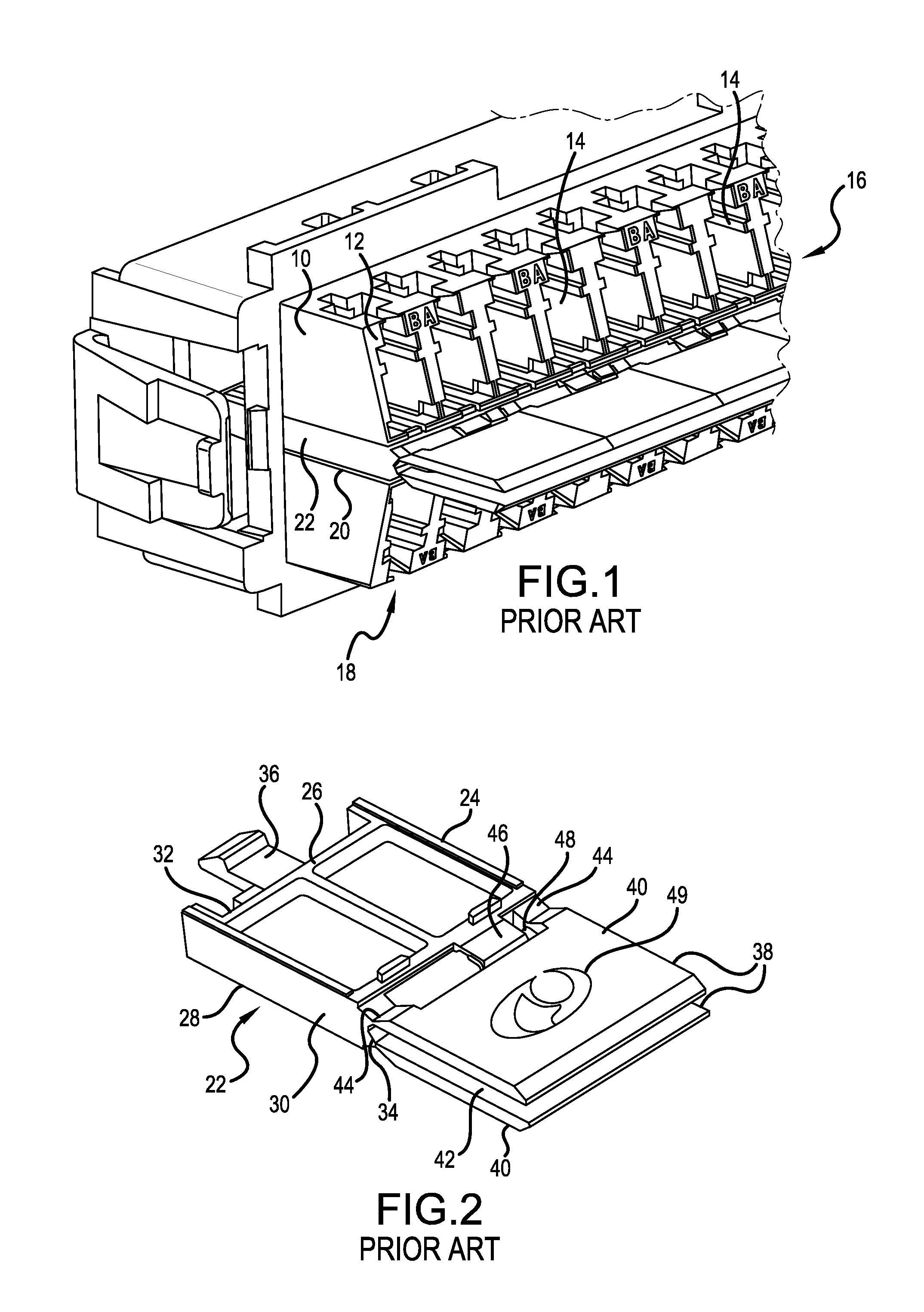
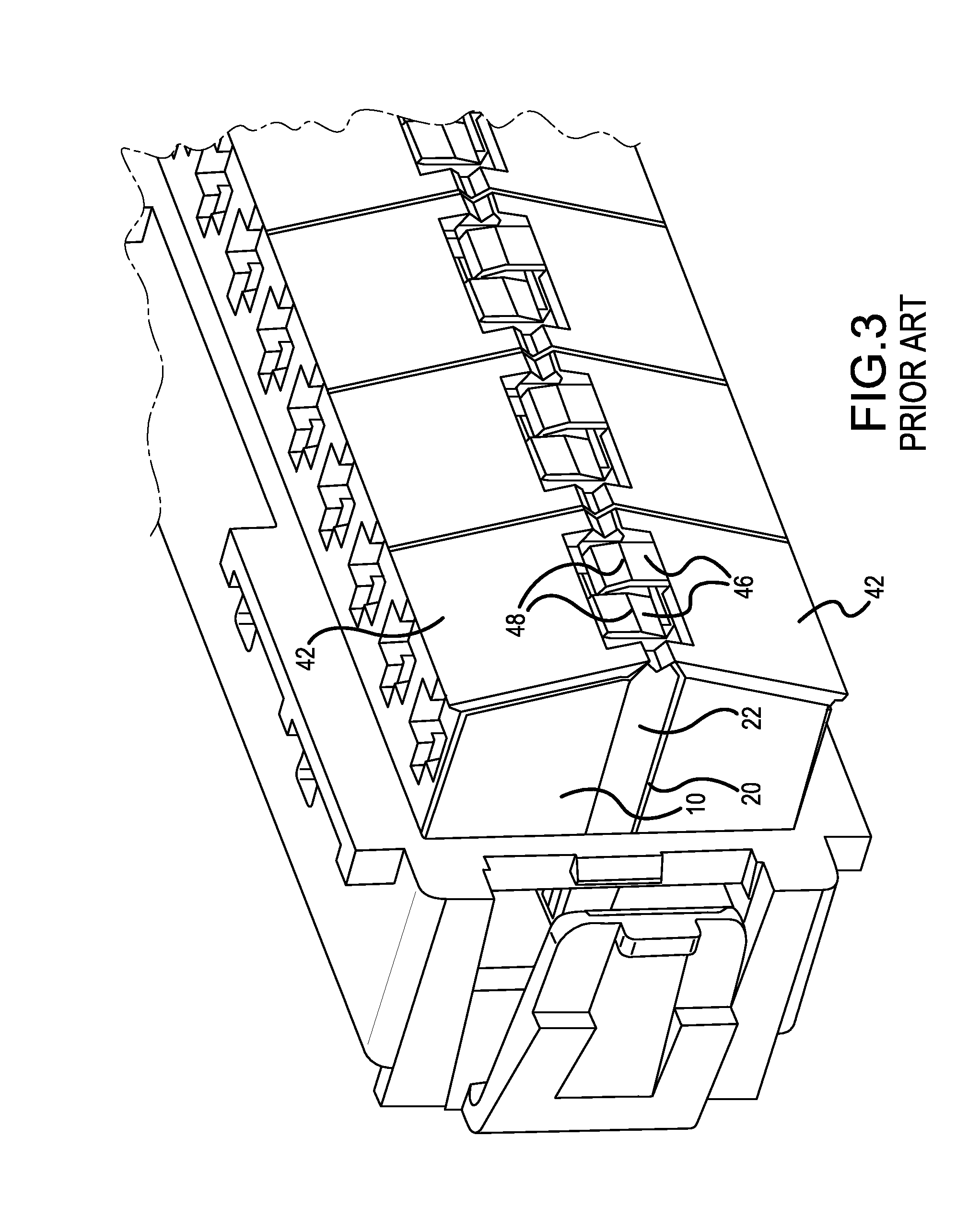
However, one drawback is that a closed shutter must first be manually opened to a point that the bi-stable hinge reaches a position tending to hold the shutter open before a fiber optic connector plug can be inserted into the port, e.g., receptacle.

Method used


Image

  • Internal shutter mechanism for a ganged fiber optic adapter
  • Internal shutter mechanism for a ganged fiber optic adapter
  • Internal shutter mechanism for a ganged fiber optic adapter

Examples


Embodiment Construction

[0034]The present invention now is described more fully hereinafter with reference to the accompanying drawings, in which embodiments of the invention are shown. This invention may, however, be embodied in many different forms and should not be construed as limited to the embodiments set forth herein; rather, these embodiments are provided so that this disclosure will be thorough and complete, and will fully convey the scope of the invention to those skilled in the art.

[0035]Like numbers refer to like elements throughout. In the figures, the thickness of certain lines, layers, components, elements or features may be exaggerated for clarity. Broken lines illustrate optional features or operations unless specified otherwise.

[0036]The terminology used herein is for the purpose of describing particular embodiments only and is not intended to be limiting of the invention. Unless otherwise defined, all terms (including technical and scientific terms) used herein have the same meaning as c...


PUM


Abstract

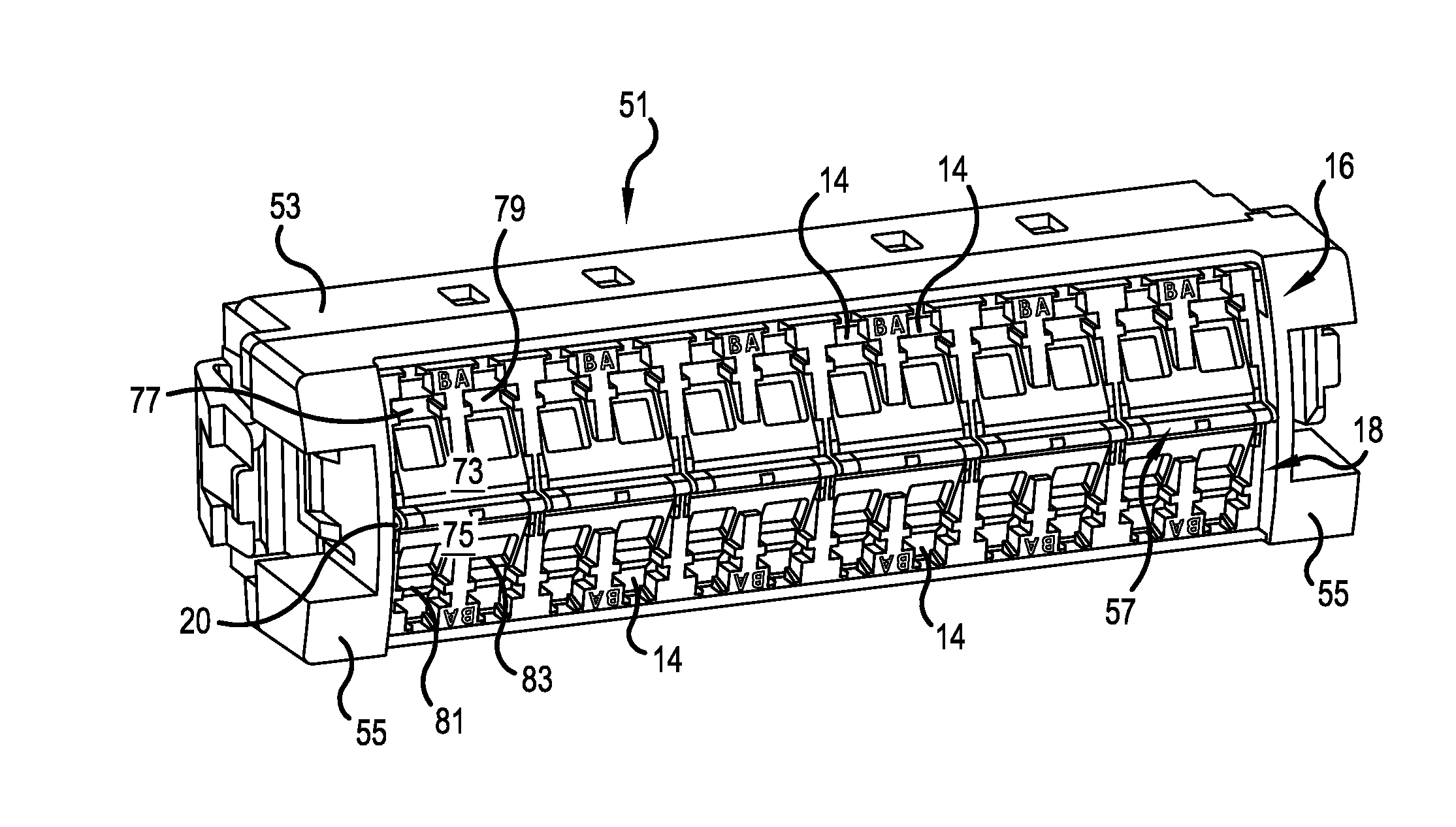
A module for a fiber optic patching system includes a housing having a front face presenting a first row of ports and a second row of ports. An opening is formed in the front face between the first and second rows of ports. A shutter assembly slides into, and is retained within, the opening. The shutter assembly includes a first shutter, which resides in front of a first port in the first row of ports, and which is movable between a first position substantially covering the first port and a second position pivoted into the first port. The shutter assembly also includes a second shutter, which resides in front of a second port in the second row of ports, and which is movable between a third position substantially covering the second port and a fourth position pivoted into the second port.

Description

[0001]This application claims the benefit of U.S. Provisional Application No. 61 / 945,046, filed Feb. 26, 2014, which is herein incorporated by reference.BACKGROUND OF THE INVENTION[0002]1. Field of the Invention[0003]The present invention relates to fiber optic connector ports. More particularly, the present invention relates to a shutter assembly which can be mounted into a port module above and below fiber optic ports, which shutter assembly has plural shutters for covering fiber optic connector ports mounted in the port module.[0004]2. Description of the Related Art[0005]One type of fiber optic organization component, such as a fiber tray, shelf, rack or panel, receives a trunk cable made up of a plurality of optical fibers. These fibers are fanned out at the organization component and individually connected to backsides of a plurality of fiber optic connector ports, e.g., receptacles. Male connectors can be plugged into the receptacles to form a connection between a fiber optic ...

Claims


Application Information

Patent Timeline
IPC IPC(8): G02B6/44G02B6/38
CPCG02B6/444G02B6/4429G02B6/3825G02B6/3849G02B6/406
Inventor TRAVIS, PETER T.
Owner COMMSCOPE INC
Why Eureka
Try Eureka