Sheet metal member having an annular peripheral wall and a method of thickening an annular peripheral wall of the sheet metal member

Active Publication Date: 2006-05-23
KANEMITSU KK
View PDF12 Cites 6 Cited by
  • Summary
  • Abstract
  • Description
  • Claims
  • Application Information

AI Technical Summary

Benefits of technology

[0006]As a result of the success of the thickening method which will be described later, in the sheet metal member of the present invention, the annular peripheral wall is thickened by a factor of 2 or more, or 3 or more which is unexpected in the prior art. Therefore, teeth, which are cut in a peripheral wall member of a drive plate of the prior art, can be directly cut in the outer face of the annular peripheral wall. Consequently, it is possible to eliminate two steps which are performed on the drive plate of the prior art, i.e., the steps of fitting the peripheral wall member 4 wherein the teeth 3 are cut, into the cylindrical portion 2 of the sheet metal member, and welding the peripheral wall member 4 to the cylindrical portion 2. Furthermore, since the base plate uses a sheet metal member which is thinner than the annular peripheral wall or has a smaller thickness, the weight and the material cost are prevented from being increased.

Problems solved by technology

Even when the peripheral wall member 4 itself has a strength and thickness sufficient for cutting the teeth 3, however, such a drive plate has problems such as defects due to welding failures which are easily produced, requiring an expensive automatic welding robot.

Method used


Image

  • Sheet metal member having an annular peripheral wall and a method of thickening an annular peripheral wall of the sheet metal member
  • Sheet metal member having an annular peripheral wall and a method of thickening an annular peripheral wall of the sheet metal member
  • Sheet metal member having an annular peripheral wall and a method of thickening an annular peripheral wall of the sheet metal member

Examples


Embodiment Construction

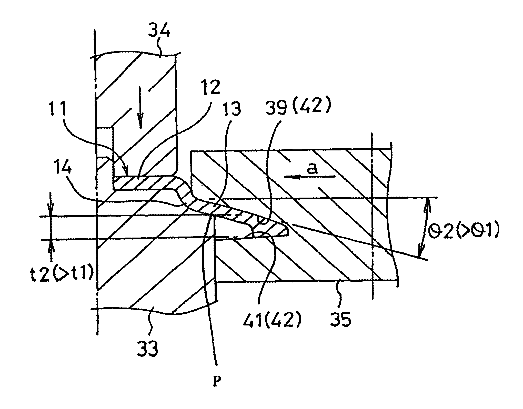
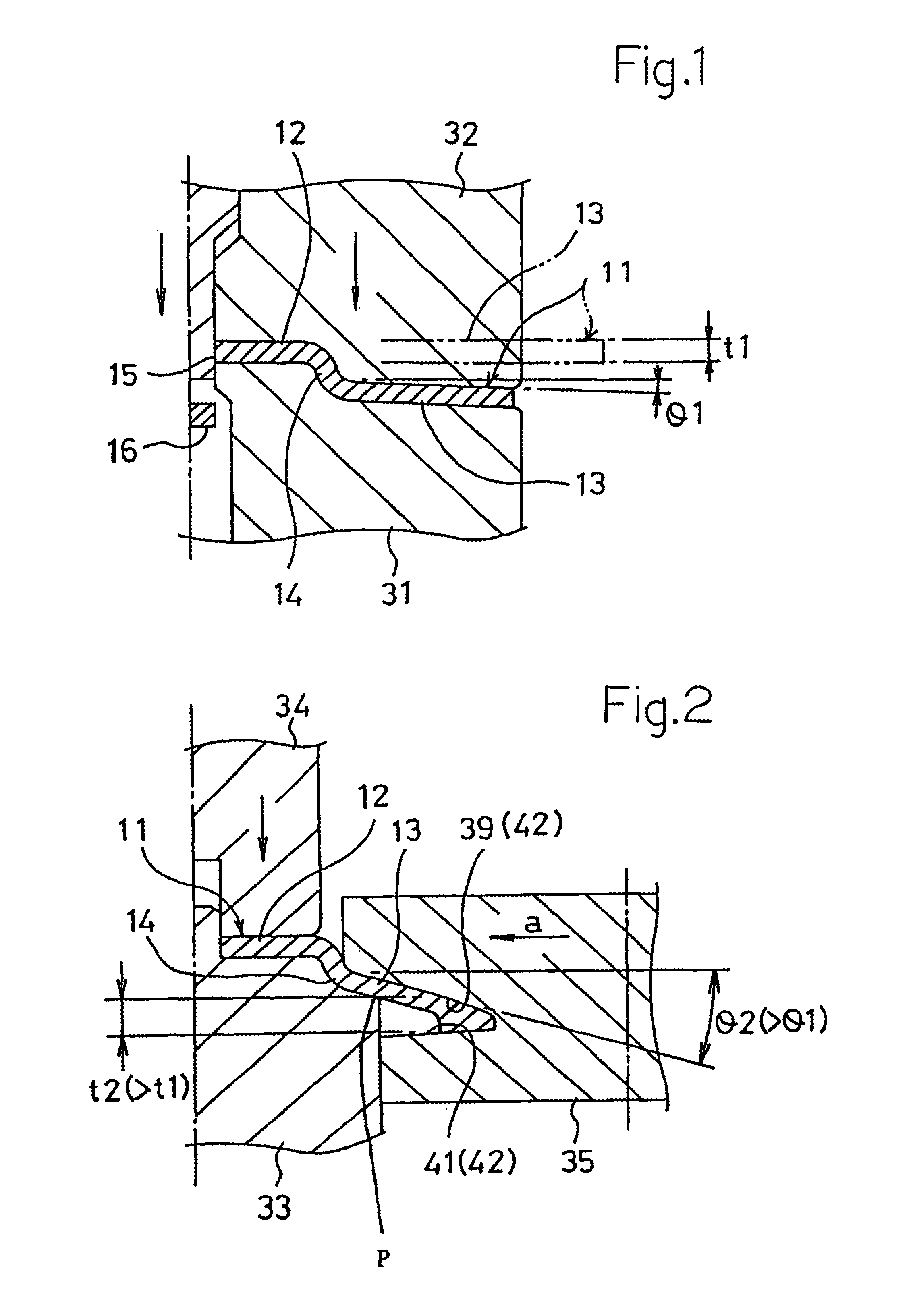
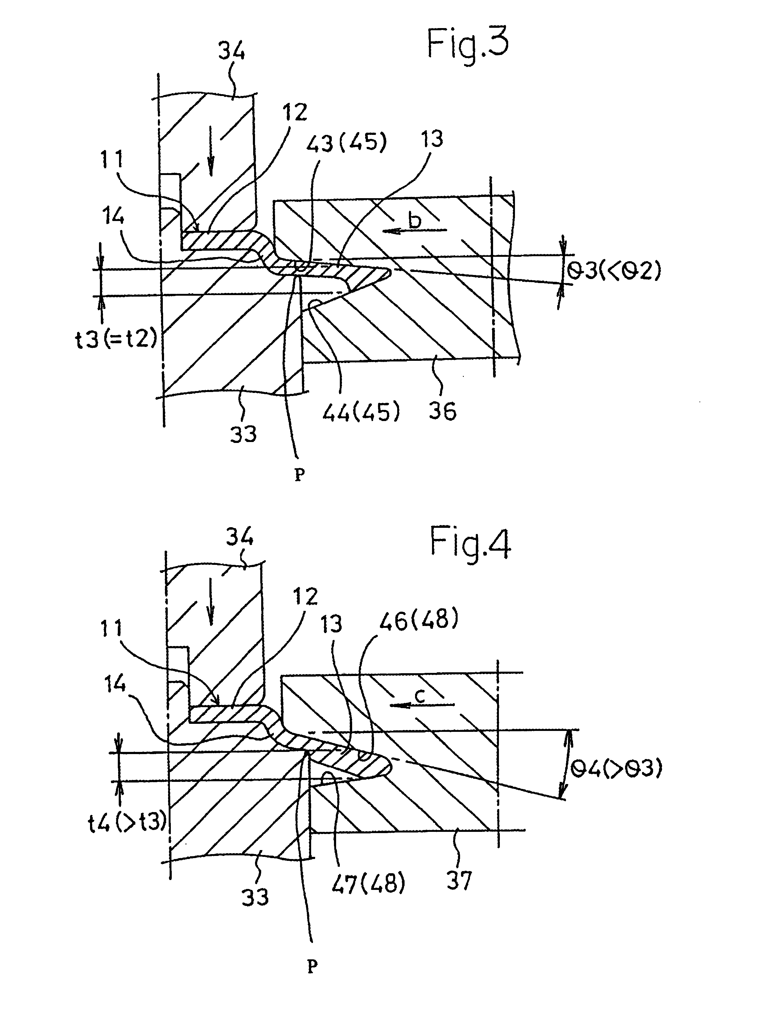
[0023]FIGS. 1 to 6 show an embodiment wherein a drive plate which is to be used in a starter for starting an engine of an automobile is produced by applying the method of thickening an annular peripheral wall according to the present invention to a thin disc member which is made of a steel plate and serves as a sheet metal member. A disc member 11 used as a starting material has a thickness t1 of 2 mm. The method of thickening an annular peripheral wall according to the present invention is applied to the disc member 11. The disc member 11 comprises a base plate 12 and a flange-shaped portion 13 which is integrated to the outer side of the base plate 12. The flange-shaped portion 13 may be continuous with the base plate 12 in a flat manner or continuous with the base plate via a stepped portion. In the embodiment, as shown in FIG. 1, the flat disc member 11 which is placed on a lower pattern tool 31 is pressed by an upper pattern tool 32, thereby drawing the disc member 11. The disc...


PUM

PropertyMeasurementUnit
Thicknessaaaaaaaaaa
Shapeaaaaaaaaaa
Strengthaaaaaaaaaa

Abstract

The present invention relates to a sheet metal member having an annular peripheral wall and a method of thickening an annular peripheral wall of the sheet metal member. The thickness of the annular peripheral wall is increased to be 2 or more times or 3 or more times that of a base plate. Teeth for a timing toothed belt, a gear, or the like are cut in the annular peripheral wall which is thickened in this way. In the method of thickening an annular peripheral wall of the present invention, a base plate integrally having a flange-shaped portion is held between a circular bottom pattern tool and a circular top pattern tool, the flange-shaped portion which projects outwardly and the circular top pattern tool is sequentially pressed in a radially inward direction by annular forming faces of circular rollers of plural kinds, thereby thickening the flange-shaped portion. The flange-shaped portion is then formed into a cylindrical shape which is concentric with the base plate. According to the method, it is not required to separately produce the peripheral wall and the base plate and then weld them together. The peripheral wall can be provided with the strength required for cutting teeth in the peripheral wall.

Description

TECHNICAL FIELD[0001]The present invention relates to a sheet metal member having an annular peripheral wall, such as a drive plate, and also to a method of thickening an annular peripheral wall of the sheet metal member, and particularly to a technique wherein a disk-shaped sheet metal member having a small thickness is used and an annular peripheral wall having a thickness which is several times the thickness of the sheet metal member. The thickened annular peripheral wall of the invention is suitable for cutting teeth to be engaged with a timing toothed belt, a gear, or the like. Teeth which are cut in this way have sufficient strength and thickness, and are suitable particularly for use as an automobile part.BACKGROUND ART[0002]In a drive plate used in a starter for starting an engine of an automobile, teeth are formed on a peripheral wall disposed in the outer peripheral portion of a disc-like base plate. FIG. 15 is a section view diagrammatically showing a prior art drive plat...

Claims


Application Information

Patent Timeline
IPC IPC(8): B21H1/04B21H1/02B21H5/02F02N15/00F16S5/00
CPCB21H1/04B21H5/02B21H1/02
Inventor KANEMITSU, TOSHIAKIKANEMITSU, SHUJINISHIOKA, HIRONORI
Owner KANEMITSU KK
Why Eureka
Try Eureka