
Solar Power Generation, Distribution, and Communication System

a technology of solar power generation and distribution, applied in emergency power supply arrangements, instruments, greenhouse gas reduction, etc., can solve the problems of conventional solar panel systems not being able to generate ac power, panel systems no longer exclusively dependent, and conventional solar panel systems being limited to generating ac outpu

Inactive Publication Date: 2015-08-27
SOLPAD INC
View PDF1 Cites 68 Cited by
  • Summary
  • Abstract
  • Description
  • Claims
  • Application Information

AI Technical Summary

Benefits of technology

The present patent is related to solar power generation and distribution systems. It describes a new system that is more efficient and flexible than conventional solar panel systems. The new system can generate and deliver both AC and DC power, and can also communicate with other devices using wireless technology. The new system is also more compact and integrated, with all components housed within a single housing. Overall, the new system offers improved performance and reliability compared to conventional solar panel systems.

Problems solved by technology

Thus, modem conventional solar panel systems are no longer exclusively dependent on the DC power collected from the conversion of solar energy to adequately sustain the power needed.
Conventional solar panel systems are limited to generating AC output power to when the conventional system is connected to the grid and receiving the AC power generated by the grid.
Conventional solar panel systems cannot generate AC power when isolated from the grid or cut off from the AC power generated by the grid.
Conventional solar panel systems are limited to generating DC output power when isolated from the grid or cut off from the AC power generated by the grid.
Further, the DC output power is inaccessible DC power in that the DC output power cannot be accessed from the conventional solar panel systems.
For example, the conventional solar panel systems fail to include a DC output power outlet in which the DC output can be accessed.

Method used


Image

  • Solar Power Generation, Distribution, and Communication System
  • Solar Power Generation, Distribution, and Communication System
  • Solar Power Generation, Distribution, and Communication System

Examples


Embodiment Construction

[0049]The following Detailed Description refers to accompanying drawings to illustrate exemplary embodiments consistent with the present disclosure. References in the Detailed Description to “one exemplary embodiment,”“an exemplary embodiment,” an “example exemplary embodiment,” etc., indicate that the exemplary embodiment described may include a particular feature, structure, or characteristic, but every exemplary embodiment may not necessarily include the particular feature, structure, or characteristic. Moreover, such phrases are not necessarily referring to the same exemplary embodiment. Further, when a particular feature, structure, or characteristic may be described in connection with an exemplary embodiment, it is within the knowledge of those skilled in the art(s) to affect such feature, structure, or characteristic in connection with other exemplary embodiments whether or not explicitly described.

[0050]The exemplary embodiments described herein are provided for illustrative...


PUM


Abstract

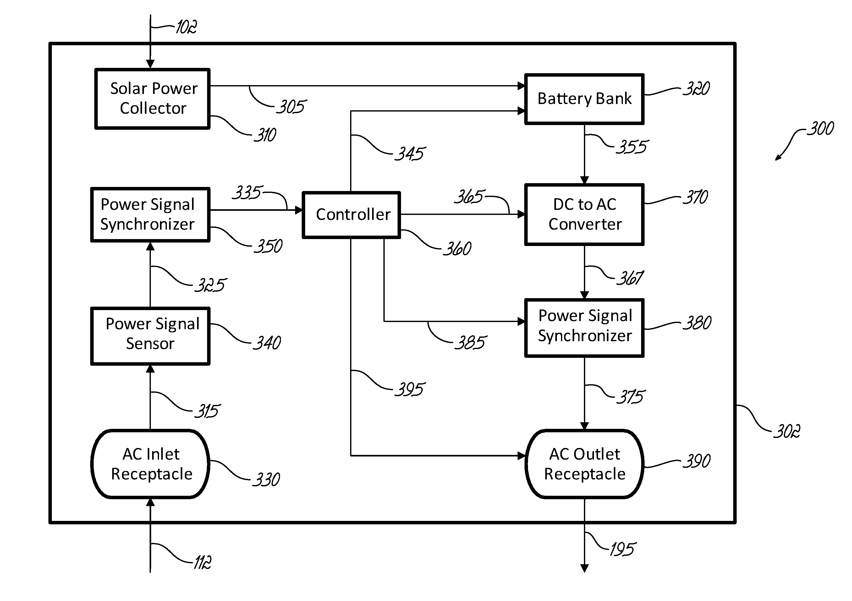
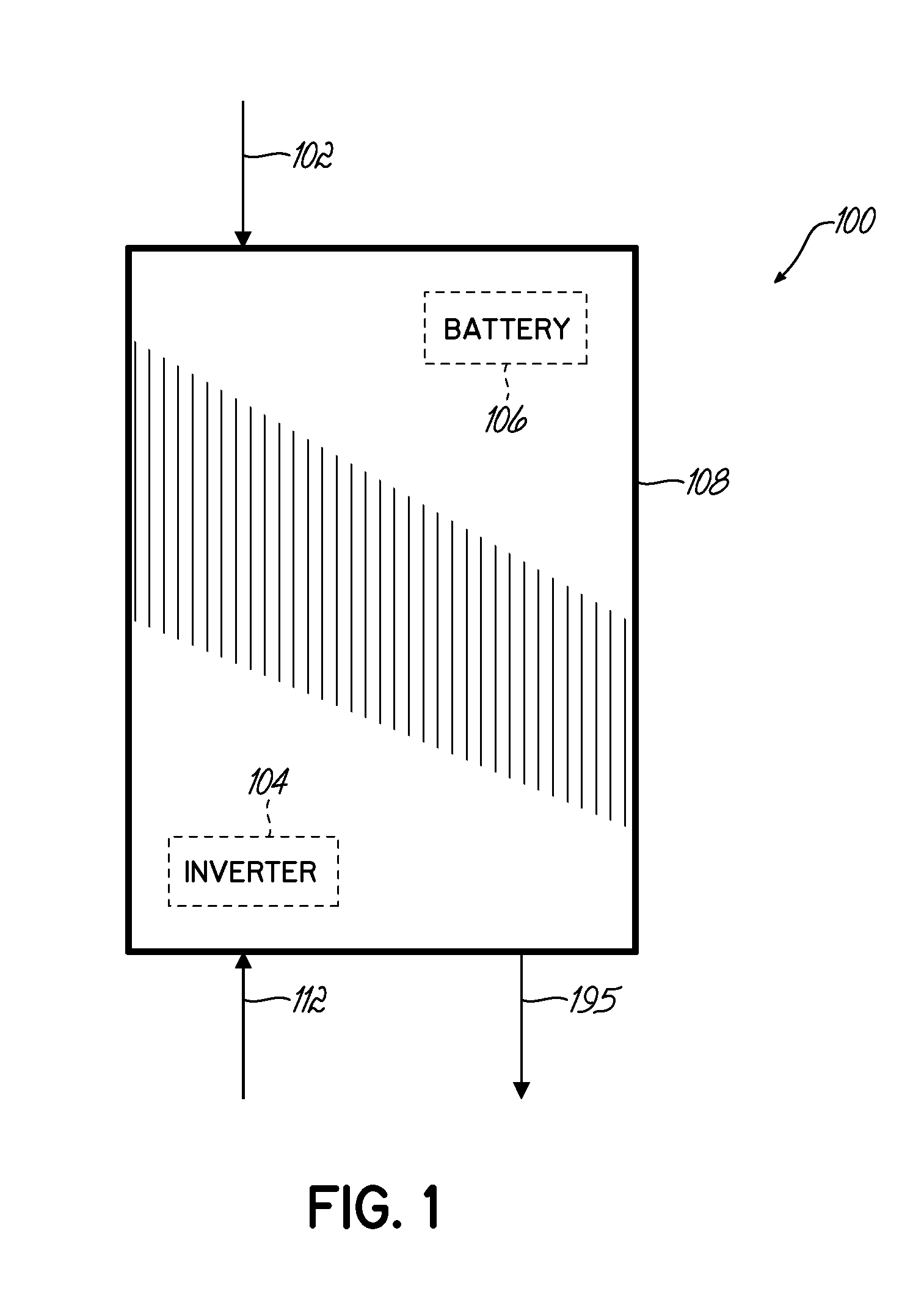
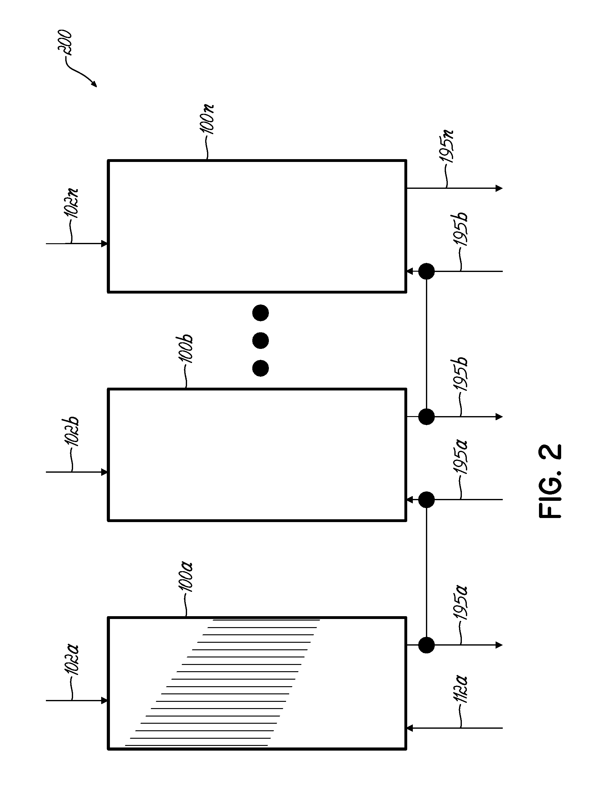
A solar panel is disclosed that can be daisy-chained with other solar panels. The solar panel automatically generates output alternative current (AC) power that is in parallel with input AC power coming into the solar panel when the solar panel senses the input AC power so that the solar panel operates as a slave in this state. The solar panel automatically generates standalone AC output power when the solar panel fails to detect input AC power coming into the solar panel where the solar panel operates as a master in this state. The solar panel generates the standalone output AC power without any reliance on input AC power generated by a utility grid and / or other AC power sources external to the solar panel.

Description

CROSS-REFERENCE TO RELATED APPLICATIONS[0001]The present application is a continuation-in-part (“C-I-P”) of and claims the benefits of U.S. patent application Ser. No. 14 / 484,488, filed Sep. 12, 2014, which was a C-I-P of and claimed the benefits of U.S. patent application Ser. No. 14 / 264,891, filed Apr. 29, 2014, which was a C-I-P of and claimed the benefits of International Application No. PCT / US14 / 28723, filed Mar. 14, 2014, which claimed the benefits of U.S. patent application Ser. No. 13 / 843,573, filed Mar. 15, 2013, which claimed the benefits of U.S. Patent Application No. 61 / 719,140, filed Oct. 26, 2012. U.S. patent application Ser. No. 14 / 264,891 is also C-I-P of and claimed the benefits of U.S. patent application Ser. No. 13 / 843,573. International Application No. PCT / US14 / 28723 also claims the benefits U.S. Patent Application No. filed 61 / 946,338, filed Feb. 28, 2015. U.S. patent application Ser. No. 14 / 484,488 is also a C-I-P of and claims the benefits of International App...

Claims


Application Information

Patent Timeline
Patent Type & Authority Applications(United States)
IPC IPC(8): H02S10/20G05B15/02
CPCG05B15/02H02S10/20H02J7/35H02J9/062H02S40/32H02S40/38H02J13/00001H02J2310/10Y02B10/70Y02B90/20Y02E10/50Y02E40/70Y02E70/30Y04S10/123Y04S20/12Y02B70/30Y04S20/248
Inventor ESTES, CHRISTOPHER A.
Owner SOLPAD INC
Learn More