
Sensors for electrical connectors

a technology of electrical connectors and sensors, applied in the field of electronic sensing systems, can solve the problems of large size and cost of existing sensing devices, inability to place devices in large numbers, and inability to meet the needs of large-scale use,

Inactive Publication Date: 2015-09-10
ALPHA & OMEGA
View PDF9 Cites 12 Cited by
  • Summary
  • Abstract
  • Description
  • Claims
  • Application Information

AI Technical Summary

Benefits of technology

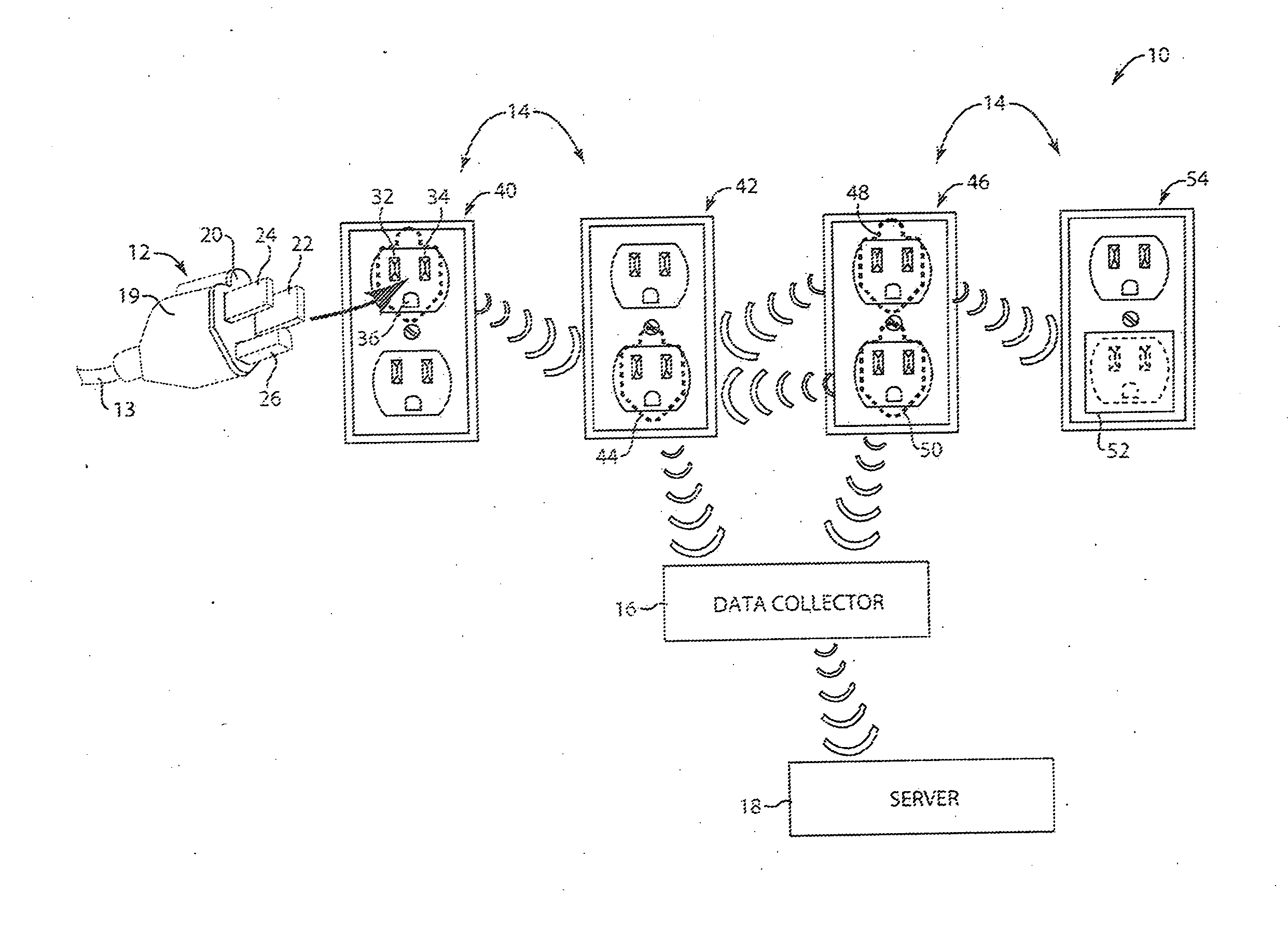
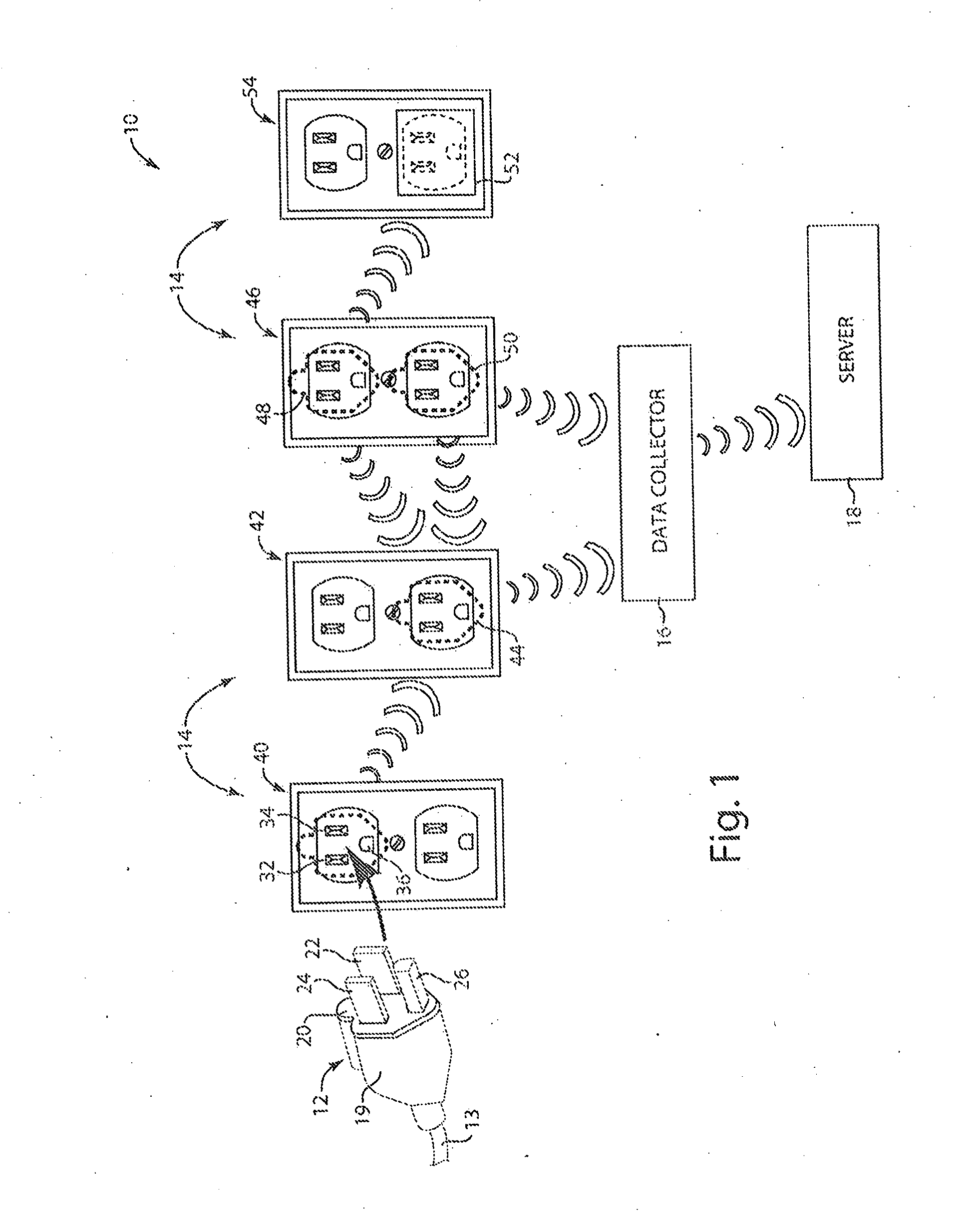
The patent describes a gasket that can be used to sense and collect data about the environment in which it is placed. The gasket includes a housing with openings that can connect to a power connector on an appliance. The gasket has a sensor that can sense various characteristics of the environment, such as the electric current flowing through the prongs of the connector. The sensor can convert the data it collects into digital signals that can be transmitted wirelessly. The gasket also has a power circuit that provides power to the sensor and the transmitter. The power circuit can receive electric current from the appliance connector. The gasket can be used to monitor power consumption and help optimize energy usage in the appliance.

Problems solved by technology

Existing sensing devices tend to be large, intrusive and cumbersome.
But this device is too large and too expensive to place in an area where space comes at a premium, nor is suitable for placement in large numbers.
However, such sensors are also of a relatively large size and often not practical to place in large numbers.
In living quarters or office space, for example, numerous such large sensors would be conspicuous and impractical.
However, this approach results in a power meter that is very bulky and is impractical to associate with many appliances, thereby resulting in incomplete information in environments having several appliances.
Further, the substantial cost of materials to produce such power meters can be a major concern.
These and other limitations of the prior art will become apparent to those of skill in the art upon a reading of the following descriptions and a study of the several figures of the drawing.

Method used


Image

  • Sensors for electrical connectors
  • Sensors for electrical connectors
  • Sensors for electrical connectors

Examples


Embodiment Construction

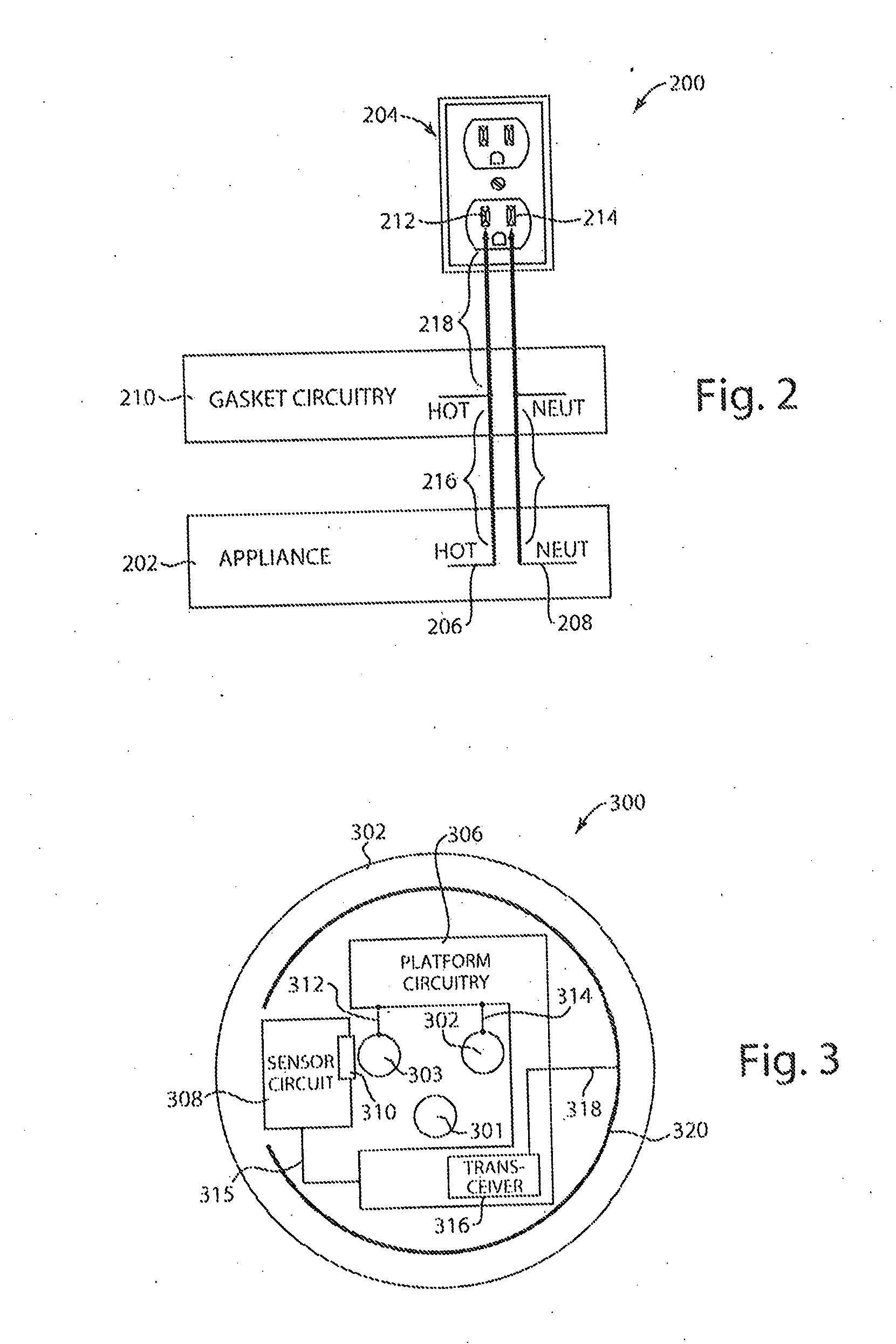
[0043]One or more implementations described herein pertain to sensing characteristics related to a connector of an appliance. In some implementations, a sensing apparatus includes a circuit board and / or housing that includes one or more openings through which prongs of an appliance connector can be inserted. One or more sensors in communication with the sensing apparatus can sense environmental characteristics, such as an electric current flowing through at least one of the prongs of the appliance connected. A transmitter of the sensing apparatus can transmit signals based on the sensed characteristics. A power circuit of the sensing apparatus can provide power from the electric current to sensing apparatus components such as the sensors, sensor circuit, and transmitter.

[0044]In some example implementations, the sensing apparatus can be included in a gasket that is slipped on the prongs of a power connector such as an AC plug of an appliance, which in turn is connected to a power su...


PUM


Abstract

In some implementations, a gasket, set forth by way of example and not limitation, includes a housing having a plurality of openings operative to receive a plurality of prongs of a power connector for an appliance. At least one sensor is operative to sense at least one characteristic of an environment. A transmitter is operative to transmit one or more signals derived from the at least one sensed characteristic, where the transmitted signals are capable of being received by a receiving device. A power circuit is operative to provide power from the electric current to the at least one sensor and the transmitter.

Description

CROSS REFERENCE TO RELATED APPLICATIONS[0001]This application is a U.S. National Stage of International Application No. PCT / US2013 / 26502, filed Feb. 15, 2013, which claims the benefit of U.S. Ser. No. 61 / 599,113, filed Feb. 15, 2012 and of U.S. Ser. No. 13 / 767,659, filed Feb. 14, 2013, all of which are incorporated by reference.FIELD OF INVENTION[0002]This invention relates generally to electronic sensors and more particularly to wireless electronic sensing systems.BACKGROUND OF INVENTION[0003]Sensing devices are used in many different applications for sensing a wide variety of different parameters or characteristics. Sensed characteristics can be used to monitor the operation of mechanical, electrical, chemical, and other phenomenon. For example, sensing devices can be capable of sensing such characteristics as temperature, pressure, electric and magnetic fields, gas and vapor concentration, odor, power, audio, and video. Some sensing devices are capable of transmitting signals ind...

Claims


Application Information

Patent Timeline
IPC IPC(8): G01R21/08G01R21/133G01R19/25
CPCG01R21/08G01R21/133G01R19/2513G01R21/00H05K1/16
Inventor AUGUSTE, DONNA M.HAYES, DAVID E.DIMMLER, KLAUS J.DEVILBISS, ALAN D.
Owner ALPHA & OMEGA
Learn More