Flippable electrical connector

a technology of electrical connectors and flip-type plugs, which is applied in the direction of coupling device connections, coupling protective earth/shielding arrangements, printed circuit aspects, etc., can solve the problem of additional degredation of super speed signals

Active Publication Date: 2015-09-10
FOXCONN INTERCONNECT TECH LTD
View PDF12 Cites 100 Cited by
  • Summary
  • Abstract
  • Description
  • Claims
  • Application Information

AI Technical Summary

Problems solved by technology

This can be costly and also cause some additional degredation in the super speed signals.

Method used


Image

  • Flippable electrical connector
  • Flippable electrical connector
  • Flippable electrical connector

Examples


first embodiment

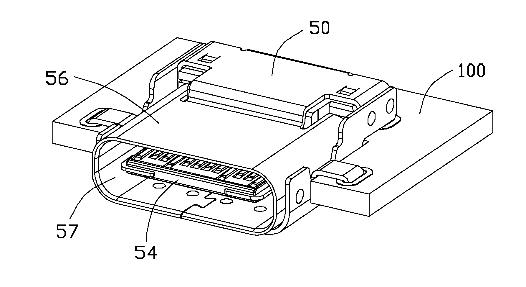
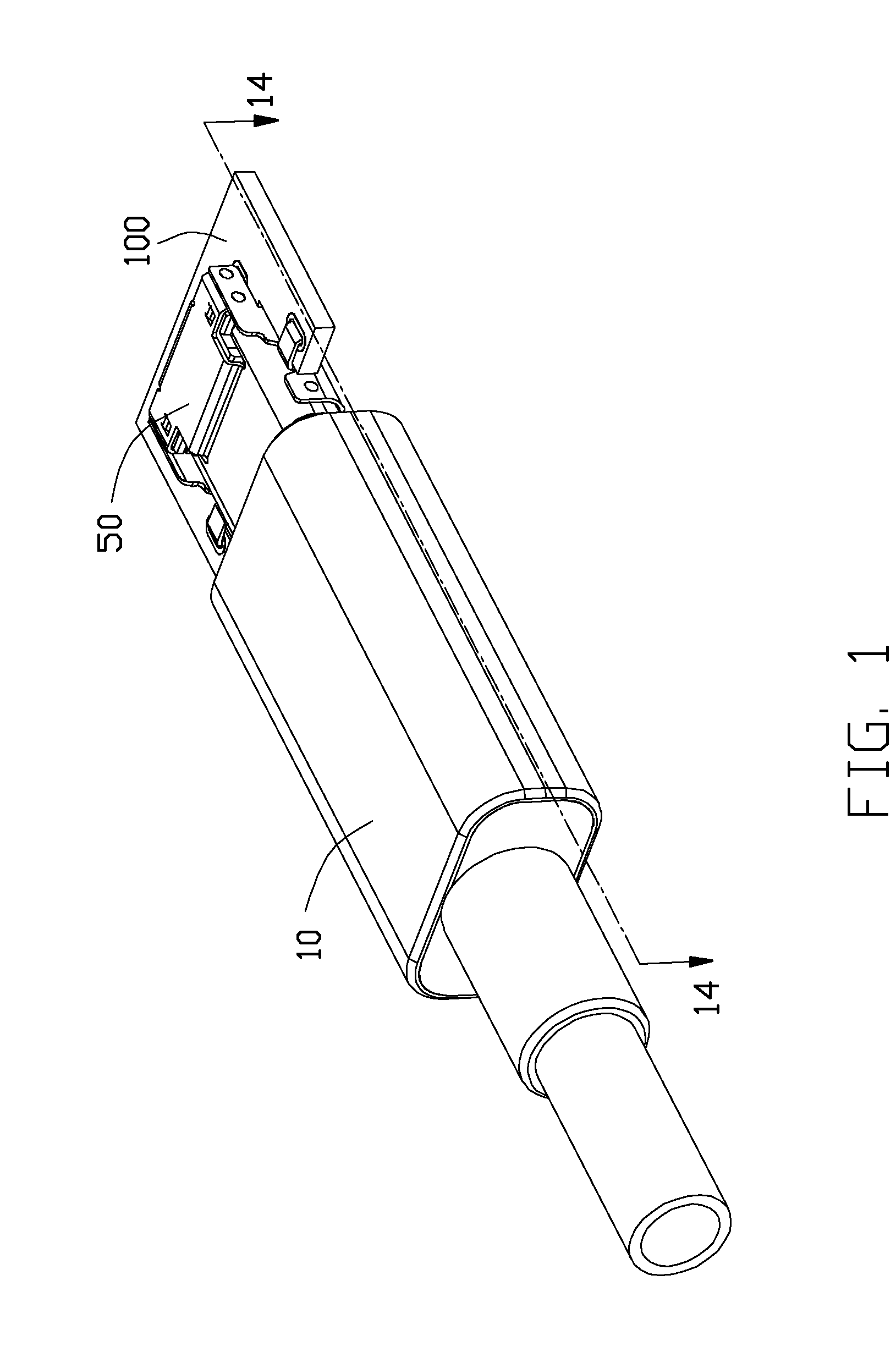
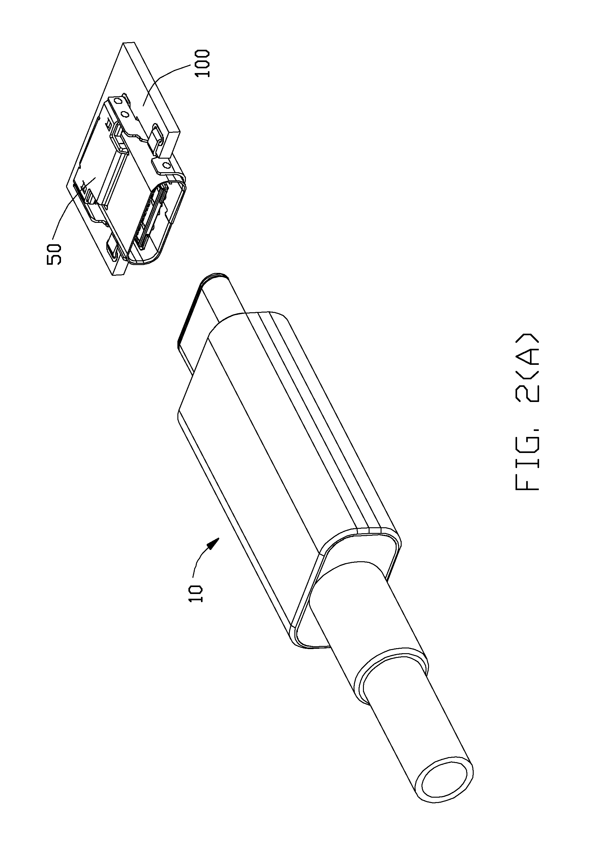
[0052]Reference will now be made in detail to preferred embodiments of the present invention. FIGS. 1-2(B) show a plug connector 10 mated with a receptacle connector 50 mounted in a notch 102 of a printed circuit board 100 of a Referring to FIGS. 3-9, the receptacle connector 50 includes an insulative housing 52 with a mating tongue 54 forwardly extending in a capsular mating cavity 57 of a metallic shield 56 which encloses the housing 52. Opposite upper and lower rows of contacts 58 are disposed in the housing 52 with corresponding contacting sections 60 exposed upon opposite surfaces of the mating tongue 54 in a diagonally symmetrical arrangement mechanically and electrically so as to allow a so-called flappable insertion of the plug connector 10 thereinto. A step structure 62 is formed around a root of the mating tongue 54. A one piece metallic EMI collar 64 includes a loop structure 66 intimately surrounding the step structure 62. The collar 64 further includes an L-shaped exte...

third embodiment

[0058]Referring to FIGS. 20-26, a water proof receptacle connector 400 of this present invention, includes a terminal module assembly 402 enclosed within a capsular metallic shield 404 which is further secured with a metallic bracket 406. A rubber / silicon outer seal 408 is located upon a circumferential exterior surface of the shield 404 around the front edge region. The terminal module assembly 402 includes a terminal module 410 essentially composed of an upper part 412 and a lower part 414 commonly sandwiching a middle part 416 therebetween. The upper part 412 includes a plurality of upper contacts 418 integrally formed with an upper insulator 420 via an insert molding process, the lower part 414 includes a plurality of lower contacts 422 integrally formed with a lower insulator 424 via another insert molding process, and the middle part 416 includes a metallic shielding plate 426 embedded within a middle insulator 428 via another insert molding process. The shielding plate 426 de...


PUM


Abstract

A receptacle connection assembly includes a printed circuit board defining two spaced slots in a front edge portion with a mating tongue formed therebetween, a plurality of pads formed on two opposite surfaces of the mating tongue in a diagonally symmetrical manner for a flippable usage and a metallic shield including a tubular capsular portion assembled to the PCB to enclose the mating tongue.

Description

CROSS REFERENCE TO RELATED APPLICATIONS[0001]This application is a continuation-in-part of the co-pending application Ser. No. 14 / 558,732 filed Dec. 3, 2014 and the instant application further claims the benefit of, and priority to, U.S. Provisional Patent Application No. 62 / 021,066, filed Jul. 4, 2014, and No. 62 / 035,472 filed Aug. 10, 2014, the contents of which are incorporated entirely herein by reference.BACKGROUND OF THE INVENTION[0002]1. Field of the Invention[0003]The present invention relates to an electrical connector, and more particularly to a flippable plug connector used with a receptacle connector.[0004]2. Description of Related Art[0005]In the previously filed provisional applications, the plug connector is “flippable” whereas we turn the plug over and it functions the same top and bottom. In order to be able to handle switching of the super speed signaling, a MUX (or SS switch) is built into the silicon. This can be costly and also cause some additional degredation ...

Claims


Application Information

Patent Timeline
Patent Type & Authority Applications(United States)
IPC IPC(8): H01R12/72H01R13/6594
CPCH01R13/6594H01R12/722H01R12/724H01R13/6658H01R24/60H01R2107/00H01R13/6585H05K1/117H05K1/184H05K2201/09063H05K2201/10189H01R13/65918
Inventor LITTLE, TERRANCE F.CHENG, CHIH-PI
Owner FOXCONN INTERCONNECT TECH LTD
Why Eureka
Try Eureka