
Apparatus for detachably securing a ladder to a shoring structure and method of use thereof

a technology for securing a portable ladder and a shoring structure, which is applied in the direction of scaffold accessories, curtain suspension devices, furniture parts, etc., can solve the problems of ladder fall, death on construction sites, and the use of slip-resistant feet as substitutes, etc., to achieve simple, cost-effective, efficient, quick and reliable manner

Active Publication Date: 2015-09-17
MARAGLIANO JOHN J
View PDF28 Cites 6 Cited by
  • Summary
  • Abstract
  • Description
  • Claims
  • Application Information

AI Technical Summary

Benefits of technology

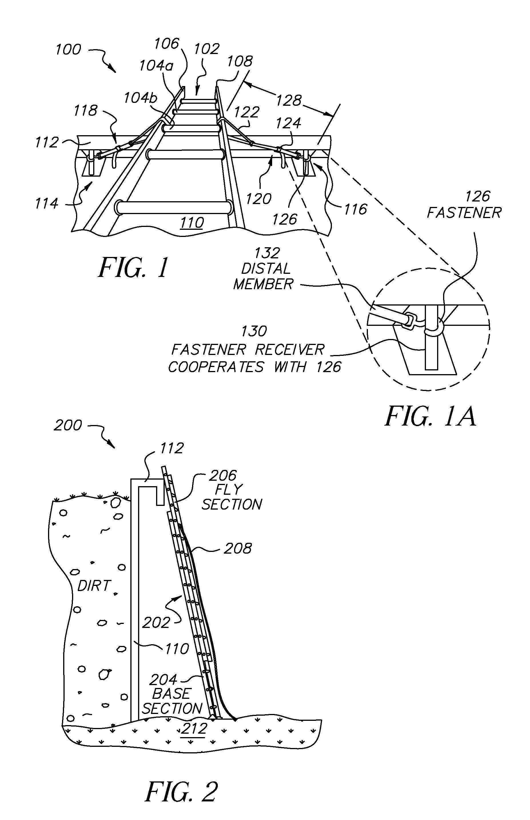
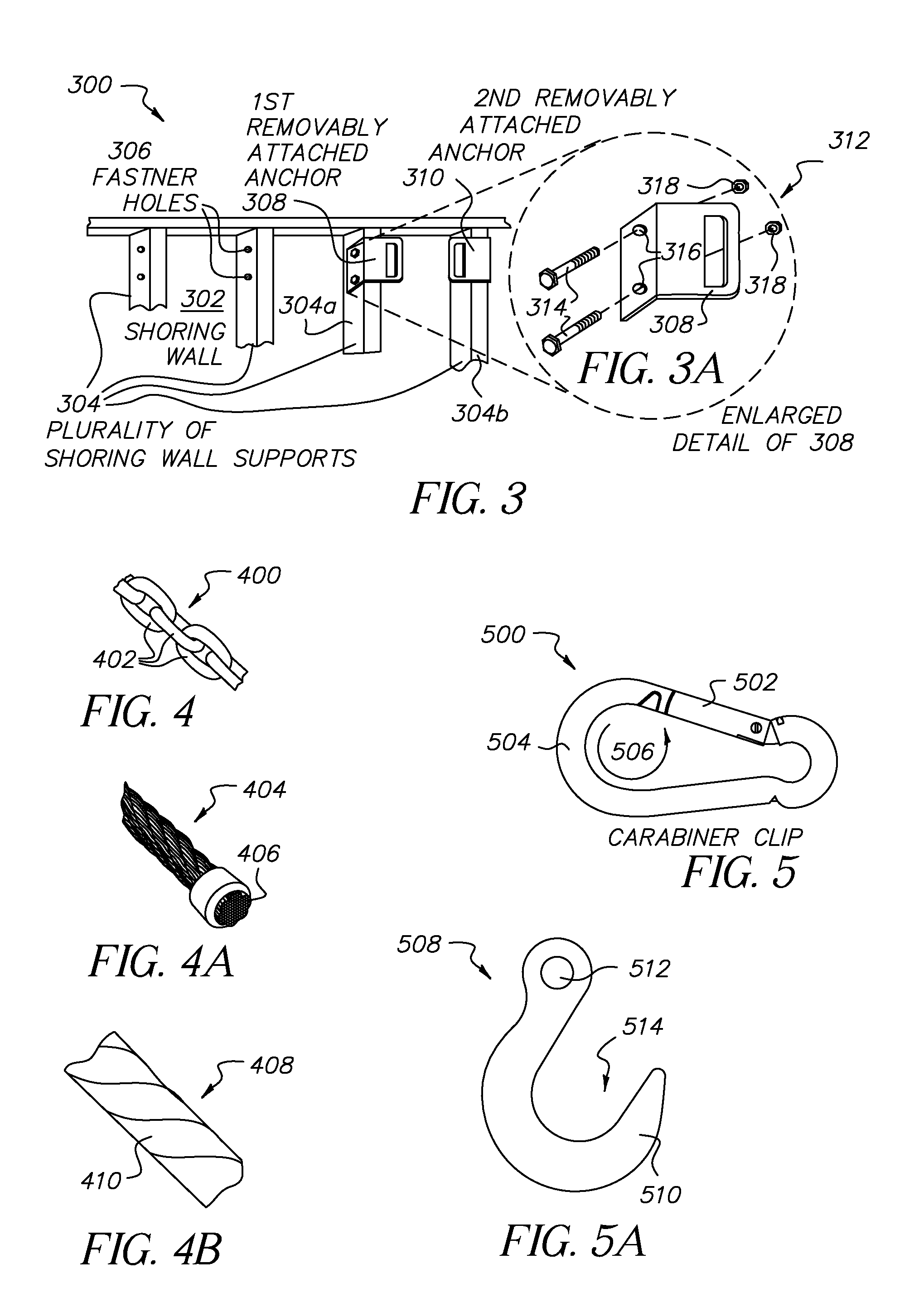
The present invention is about a restraining system for securing a ladder to a shoring or excavation support structure. It is made up of an elongated flexible restraining material with fasteners on each end that attach to the ladder and the shoring wall. A tensioning means is included to adjust the length of the restraining material. The system has several embodiments, including a shoring wall with multiple shoring anchors for easy relocation or additional ladder access locations. The restraining assembly is simple to install and remove, and it is made from high-strength materials. The system is economical and susceptible to low manufacturing costs. Overall, the invention provides a safe and effective way to secure a ladder to a shoring or excavation support structure.

Problems solved by technology

Falls from ladders are the leading cause of deaths on construction sites.
Slip-resistant feet shall not be used as a substitute for care in placing, lashing, or holding a ladder that is used upon slippery surfaces including, but not limited to, flat metal or concrete surfaces that are constructed so they cannot be prevented from becoming slippery.

Method used


Image

  • Apparatus for detachably securing a ladder to a shoring structure and method of use thereof
  • Apparatus for detachably securing a ladder to a shoring structure and method of use thereof
  • Apparatus for detachably securing a ladder to a shoring structure and method of use thereof

Examples


Embodiment Construction

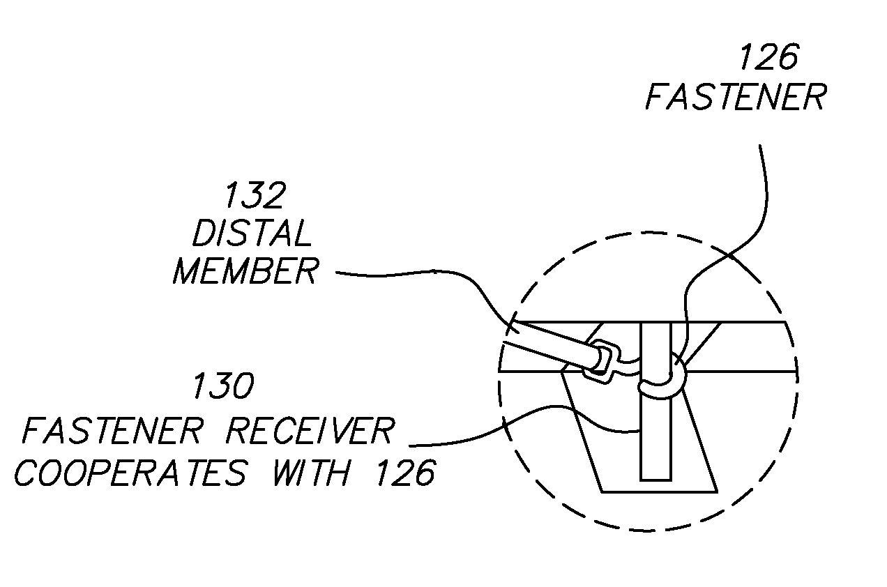
[0102]With reference to the drawings of the present invention, several embodiments pertaining to the apparatus for detachably securing a ladder to a shoring structure and method of thereof will be described. In describing the embodiments illustrated in the drawings, specific terminology will be used for the sake of clarity. However, the invention is not intended to be limited to the specific terms so selected, and it is to be understood that each specific term includes all technical equivalents that operate in a similar manner to accomplish a similar purpose. Terminology of similar import other than the words specifically mentioned above likewise is to be considered as being used for purposes of convenience rather than in any limiting sense.

[0103]It must be noted that as used herein and in the appended claims, the singular forms “a”, “an”, and “the” include plural reference unless the context clearly dictates otherwise. As well, the terms “a” (or “an”), “one or more” and “at least o...


PUM

PropertyMeasurementUnit
flexibleaaaaaaaaaa
lengthaaaaaaaaaa
abrasive forcesaaaaaaaaaa

Abstract

A restraining system and method for detachably securing a ladder to a shoring or excavation support structure. The restraining assembly, primarily configured from an elongated flexible restraining material, includes a proximal member, possessing a fastener configured to removably attach onto either side rail of a ladder. The assembly further includes a distal member, possessing a fastener configured to removably attach to a shoring anchor located on the top portion of a shoring wall. The mediate portion of the restraining assembly is configured to concurrently retain both the proximal and distal members, including a tensioning means for the adjustment of the overall functional length of the restraining assembly. In particular embodiments, the restraining system includes a shoring or excavation support structure having at least one shoring wall that includes a multiplicity of shoring anchors attached at predetermined locations.

Description

FIELD OF THE INVENTION[0001]This invention generally relates to a safety device or safety system for use on shoring structures or excavation support structures. In a more specific aspect, the present invention is primarily directed to an apparatus for detachably securing a portable ladder to a shoring wall that comprises a shoring structure.BACKGROUND OF THE INVENTION[0002]According to the World Health Organization, the United States leads the world in ladder deaths. Each year, in the United States, there are more than 164,000 emergency room visits and 300 deaths associated with falls from ladders. Falls from ladders are the leading cause of deaths on construction sites.[0003]The United States Code of Federal Regulations (CFR), more specifically—section 29CFR 1926.1053, sometimes generally referred to as OSHA 1926, includes numerous regulations directed to ladder safety. With respect to safe ladder use, the CFR specifies that when portable ladders are used for access to an upper lan...

Claims


Application Information

Patent Timeline
Patent Type & Authority Applications(United States)
IPC IPC(8): E06C7/50
CPCE06C7/505E06C7/188Y10T29/49947
Inventor MARAGLIANO, JOHN J.
Owner MARAGLIANO JOHN J
Learn More