

Near-infrared cut filter
a filter and near-infrared technology, applied in the field of near-infrared filter, can solve the problems of insufficient insufficient transmitting properties of wavelength bands (630 nm to 700 nm), and insufficient performance for shielding light of wavelengths in the near-infrared region. , to achieve the effect of excellent near-infrared absorbing properties and high solubility to resin
- Summary
- Abstract
- Description
- Claims
- Application Information
AI Technical Summary
Benefits of technology
Problems solved by technology
Method used
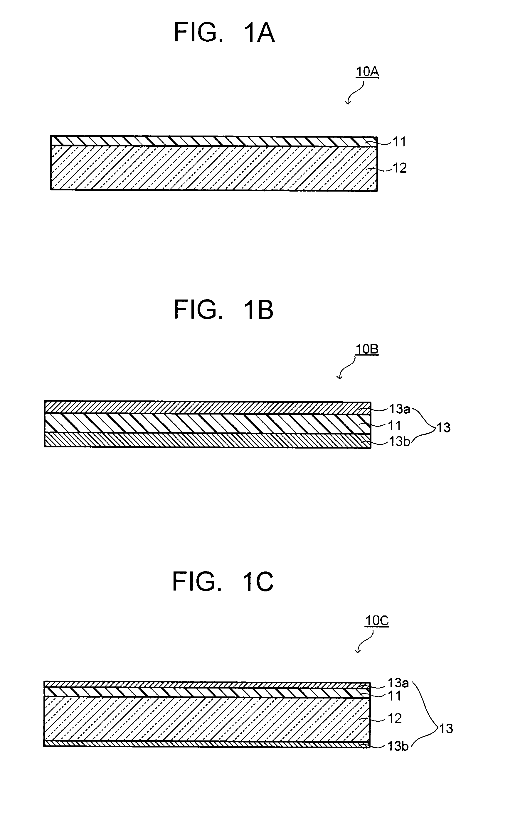
Image

Examples
example 1 to example 75
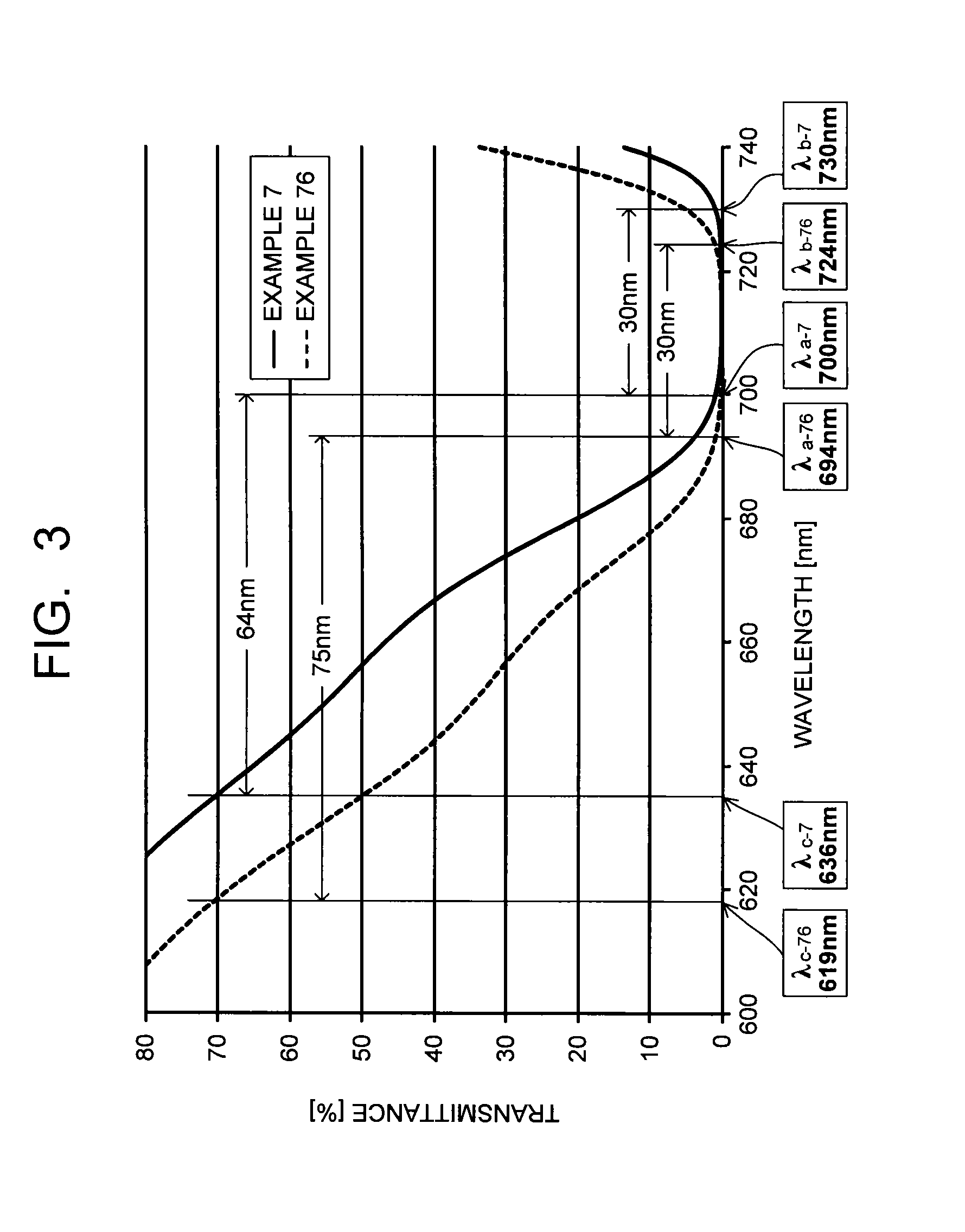
[0254]As described in Table 4, one of the dyes (A11-1) to (A11-19) and a 15 mass % cyclohexanone solution of the polyester resin were mixed, and stirred and solved at room temperature to obtain a coating liquid. In any case, the dyes (A11-1) to (A11-19) were mixed by a content which causes (λb−λa) (absorption width when the transmittance is 1% or less) defined in the above condition (ii-2) to be 30 nm with a film thickness of 3 μm or less to 100 parts by mass of the polyester resin. As the polyester resin, B-OKP2 (product name, made by Osaka Gas Chemicals Co., Ltd., refractive index 1.64) was used.
[0255]The coating liquid obtained above was applied on a glass plate by a spin coat method and dried at 90° C. for five minutes, and thereafter an obtained sample was further dried at 150° C. for 60 minutes, thereby obtaining NIR filters of Example 1 to Example 17. The film thicknesses of the near-infrared absorbing layers of the obtained NIR filters 1 to 17 were all 2.7 μm.
[0256]NIR filte...
example 76 to example 109
[0265]As described in Table 7 and Table 8, one of the dyes (A11-20) to (A11-27) and the transparent resin (B) were used to obtain NIR filters 76 to 109 of Example 76 to Example 109. The film thicknesses of the near-infrared absorbing layers of the respective NIR filters are the same film thicknesses as those of respective examples of the examples that use the same transparent resin (B).
[0266]
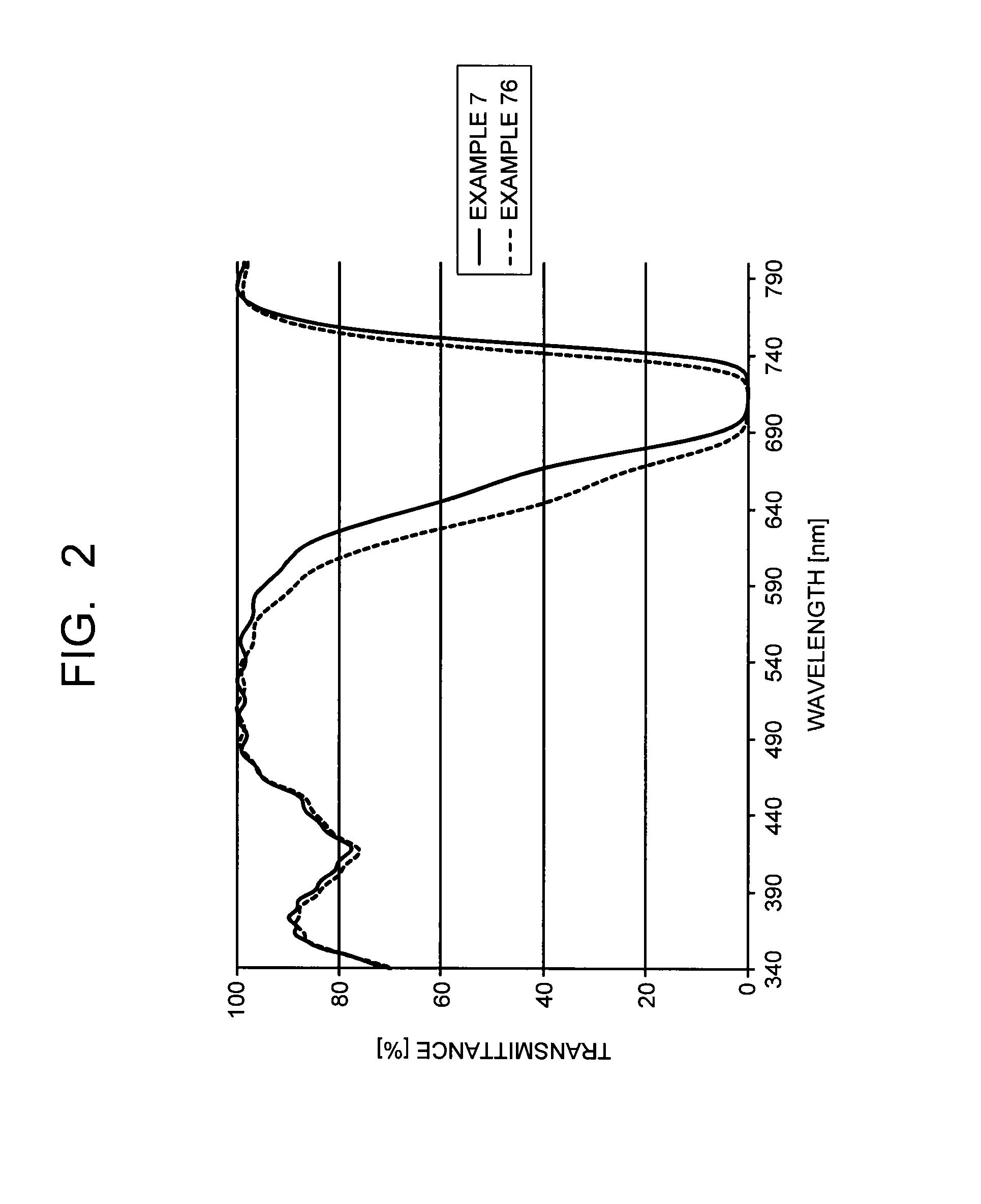
[0267](1) Absorption Characteristics
[0268]Regarding transmittance (% / nm) of the NIR filters 1 to 109 obtained above, transmission spectra were measured and calculated by using an ultraviolet visible light spectrophotometer (U-4100 type spectrophotometer made by Hitachi High-Technologies Corporation). Analysis results of transmission spectra of the near-infrared absorbing layers which the NIR filters have are presented in Table 4, Table 5 and Table 6 for the NIR filters 1 to 25, 26 to 51, 52 to 75, respectively, and are presented in Table 7 and Table 8 for the NIR filters 76 to 94, 95 to 109, res...
example 110
[0285]The near-infrared absorbing layer was formed on a glass plate similarly to Example 7 except that a glass plate on which the selected wavelength shielding layer is formed was used on a face opposite to an application face of the coating liquid for forming the near-infrared absorbing layer. Moreover, the antireflection layer was formed on the near-infrared absorbing layer, so as to obtain the NIR filter 110. The film thickness in the selected wavelength shielding layer in its entirety was approximately 8.9 μm, and the film thickness in the antireflection layer in its entirety was approximately 0.34 μm. The transmittance of the obtained NIR filter 110 was measured, and 20% shifts (30 degrees) and (40 degrees) were obtained. Results thereof are presented in Table 9 together with structures of the near-infrared absorbing layer. FIG. 6 illustrates transmission spectra of light with incident angles of 0 degree, 30 degrees and 40 degrees of the wavelength region of 660 nm to 690 nm in...
PUM
| Property | Measurement | Unit |
|---|---|---|
| refractive index | aaaaa | aaaaa |
| wavelength | aaaaa | aaaaa |
| wavelength | aaaaa | aaaaa |
Abstract
Description
Claims
Application Information