Hybrid vehicle drive system

a hybrid vehicle and drive system technology, applied in the direction of engine-driven generator propulsion, transportation and packaging, propulsion parts, etc., can solve the problems of time-consuming and complicated drive mode switching operations, and achieve the effect of reducing the deterioration of the drivability of the hybrid vehicle and efficient switching

Active Publication Date: 2015-09-24
TOYOTA JIDOSHA KK
View PDF8 Cites 8 Cited by
  • Summary
  • Abstract
  • Description
  • Claims
  • Application Information

AI Technical Summary

Benefits of technology

[0013]The hybrid vehicle drive system according to the third aspect of the invention is constructed such that the drive system is switched from the first-speed or second-speed constant-speed-ratio engine drive mode to the first electric motor drive mode, and from the third-speed or fourth-speed constant-speed-ratio engine drive mode to the second electric motor drive mode. Thus, the drive

Problems solved by technology

However, the prior art hybrid vehicle has a problem of complicated and time-consuming drive mode switching operations involving repeated changes of the operating states of select

Method used


Image

  • Hybrid vehicle drive system
  • Hybrid vehicle drive system
  • Hybrid vehicle drive system

Examples


Embodiment Construction

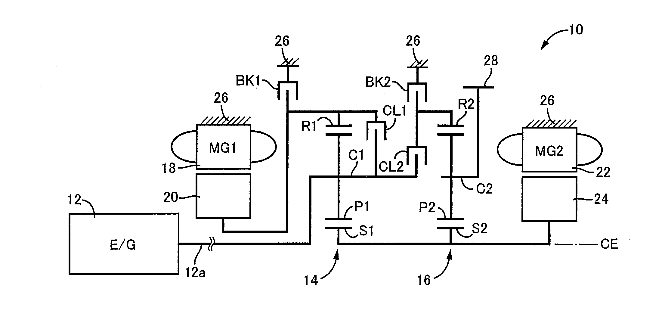
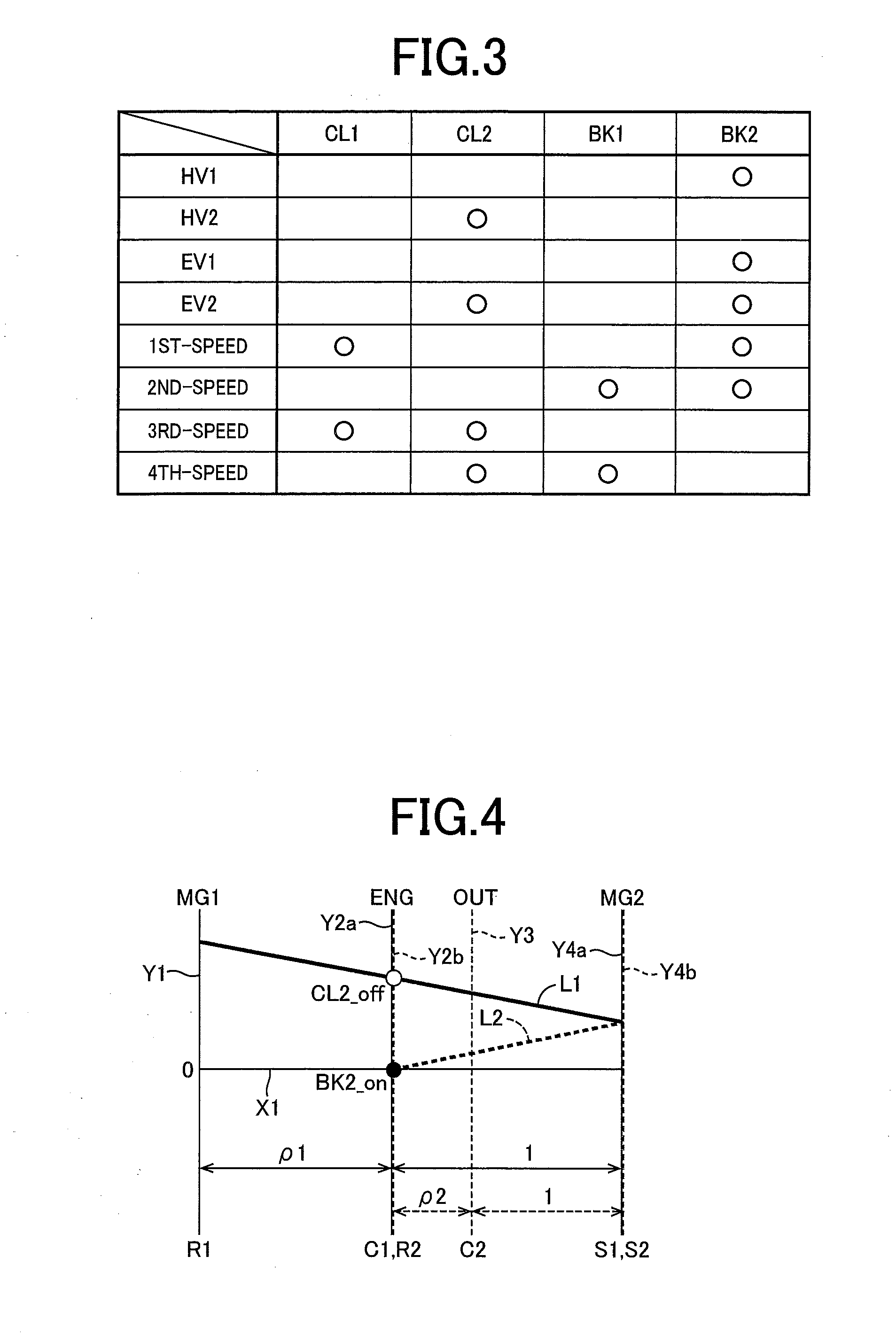
[0026]In the hybrid vehicle drive system according to the present invention, the differential device comprising the first differential mechanism and the second differential mechanism comprises the four rotary components when the coupling element (second clutch) disposed between a rotary element of the first differential mechanism and a rotary element of the second differential mechanism is placed in an engaged state. Preferably, the differential device comprises the four rotary components when the coupling element (second clutch) disposed between a second rotary element of the first differential mechanism and a first rotary element of the second differential mechanism is placed in the engaged state. In other words, the present invention is suitably applicable to a hybrid vehicle drive system including: a differential device comprising a first differential mechanism and a second differential mechanism and comprising four rotary components relative rotating speeds of which are represe...


PUM


Abstract

A hybrid vehicle drive system, which permits an efficient change of a vehicle drive mode from any one of constant-speed-ratio engine drive modes to one of electric motor drive modes, with reduced deterioration of drivability of the hybrid vehicle. The hybrid vehicle drive system is constructed such that one of the electric motor drive modes can be established by releasing one of two coupling elements which are placed in the engaged state in a presently established one of the constant-speed-ratio engine drive modes, when the drive system is required to be switched from the above-described one of the constant-speed-ratio engine drive modes to any one of the electric motor drive modes, whereby the drive system can be efficiently switched from any one of the constant-speed-ratio engine drive modes to the above-indicated one of the electric motor drive modes, by simply releasing one of the above-indicated two coupling elements.

Description

CROSS REFERENCE TO RELATED APPLICATION[0001]The present application claims the priority from Japanese Patent Application No. 2014-060883 filed on Mar. 24, 2014, the disclosure of which is herein incorporated by reference in its entirety.BACKGROUND OF THE INVENTION[0002]1. Field of the Invention[0003]The present invention relates to an improvement of a drive system of a hybrid vehicle.[0004]2. Description of Related Art[0005]There is known a hybrid vehicle including: a differential device which comprises a first differential mechanism and a second differential mechanism and which comprises four rotary components; an engine, a first electric motor, a second electric motor and an output rotary member which are respectively connected to the four rotary components; and a plurality of coupling elements which are provided to selectively connect the rotary components to each other or to a stationary member, to establish a selected one of a plurality of electric motor drive modes and a plura...

Claims


Application Information

Patent Timeline
IPC IPC(8): B60W10/02B60W10/12B60W20/00B60W10/08B60L50/16
CPCB60W10/02B60W10/08Y10S903/902B60W20/00B60W10/12B60K6/365B60K6/387B60K6/445B60W10/06B60K2006/381B60W20/10B60W20/40Y02T10/62
Inventor SAHASHI, JUNICHIROSUZUKI, HIROKAZU
Owner TOYOTA JIDOSHA KK
Why Eureka
Try Eureka