Light bulb having light emitting diodes connected to at least two circuit boards

Inactive Publication Date: 2015-09-24
HUANG TAI HSIANG +1
View PDF0 Cites 10 Cited by
  • Summary
  • Abstract
  • Description
  • Claims
  • Application Information

AI Technical Summary

Benefits of technology

The technical effect of this patent is that it describes an improved system for controlling electronic devices by using handheld control units. These control units can be used to send commands to different components within the device, allowing users to interact with them more easily. This makes the use of these devices much simpler and user-friendly.

Problems solved by technology

The technical problem addressed in this patent is how to create a light bulb where the LEDs can be arranged at different angles to produce more complete coverage of the area around the lamp without compromising its brightness or energy-efficient performance.

Method used


Image

  • Light bulb having light emitting diodes connected to at least two circuit boards
  • Light bulb having light emitting diodes connected to at least two circuit boards
  • Light bulb having light emitting diodes connected to at least two circuit boards

Examples


Embodiment Construction

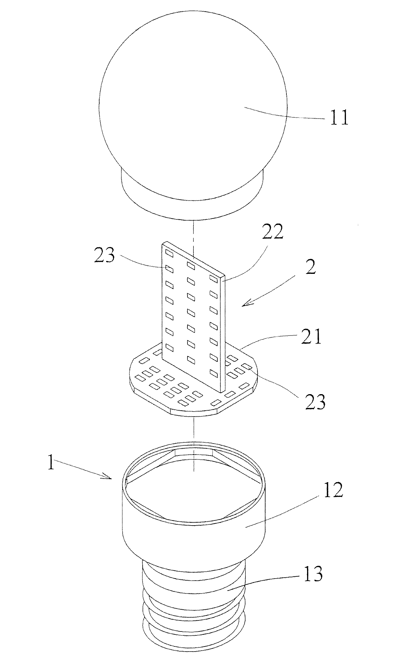
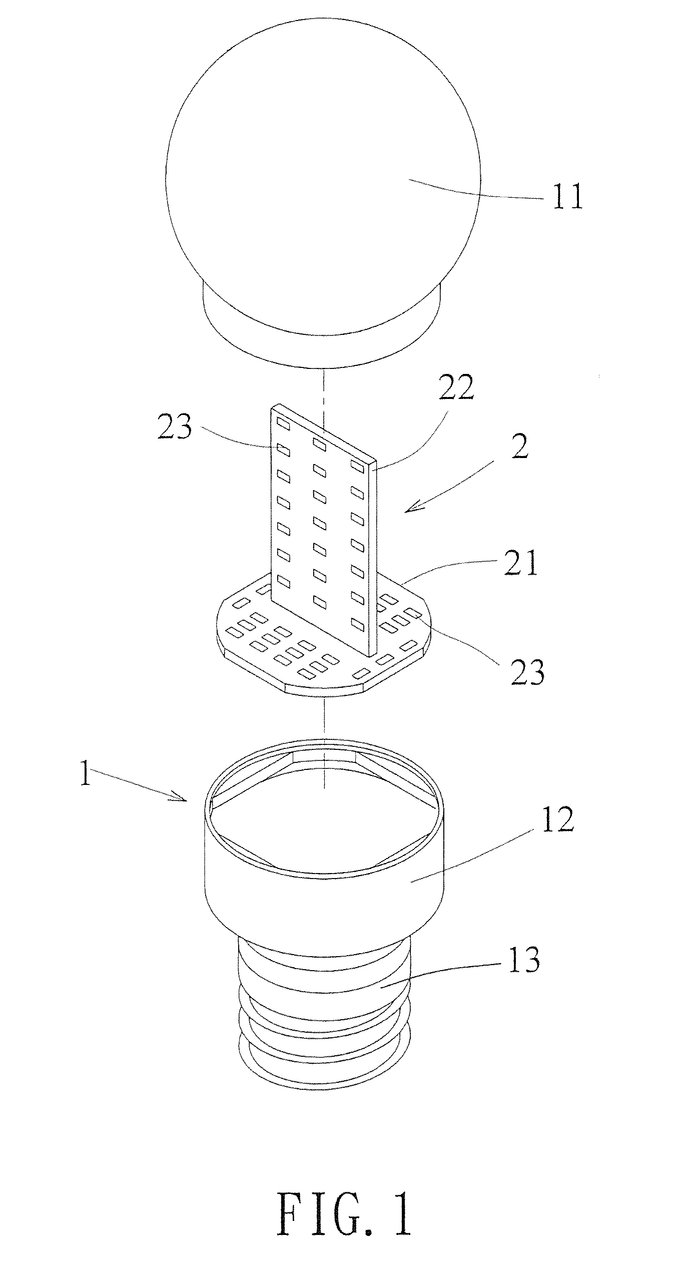
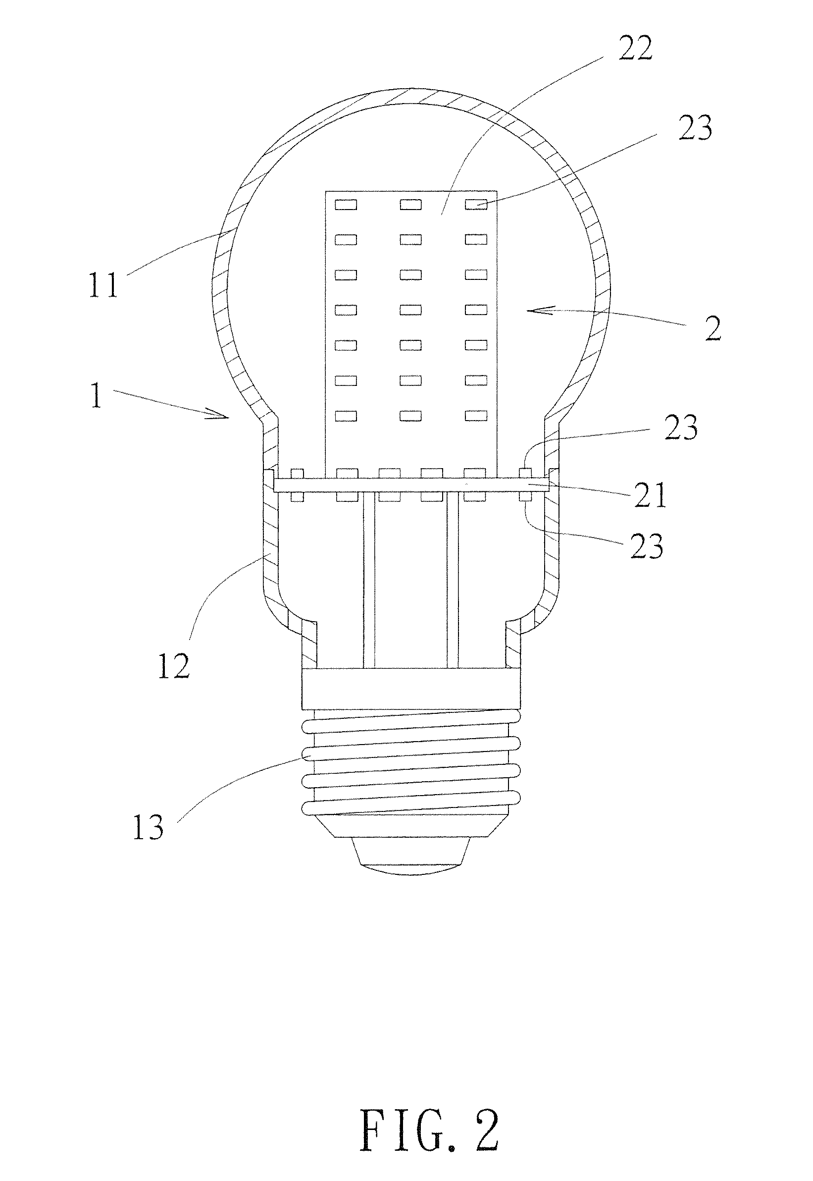
[0017]Referring to FIGS. 1 and 2, the light bulb of the present invention comprises a glass bulb 1 and a light unit 2. The glass bulb 1 has a top part 11 and a bottom part 12 which is connected to the top part 11 so as to define a space between the top and bottom parts 11, 12. The light unit 2 is located in the space. The bottom part 12 is connected to a screw cap 13 which is electrically connected with the light unit 2. Electric power is supplied to the light unit via the screw cap 13.

[0018]The light unit 2 has a transverse circuit board 21 and an upright circuit board 22. Multiple Light Emitting Diodes 23 are connected to the top surface and the bottom surface of the transverse circuit board 21. The upright circuit board 22 is connected to the top surface of the transverse circuit board 21. Multiple Light Emitting Diodes 23 are connected to the outside surface of the upright circuit board 22.

[0019]FIGS. 3 and 4 show the second embodiment of the light bulb of the present invention,...


PUM


Abstract

A light bulb includes a glass bulb having a top part and a bottom part which is connected to the top part. A light unit is located in a space defined between the top and bottom parts. The light unit has a transverse circuit board and at least one upright circuit board. Multiple Light Emitting Diodes are connected to the top surface and the bottom surface of the transverse circuit board. The at least one upright circuit board is connected to the top surface of the transverse circuit board. Multiple Light Emitting Diodes are connected to the outside surface of the at least one upright circuit board.
The light beams from the Light Emitting Diodes go through the glass bulb and toward different directions.

Description


Claims


Application Information

Patent Timeline
Owner HUANG TAI HSIANG
Why Eureka
Try Eureka