Apparatus For Producing Foamed Bitumen And Method For Its Maintenance

a technology for producing apparatus and foamed bitumen, which is applied in the direction of cleaning process, apparatus, and way, can solve the problems of inability to precisely dose foam, clogging of inlet and outlet devices, and especially the provided injection nozzles, and no longer working upon re-start, so as to achieve more cost-effective and reliable production and operation.

Active Publication Date: 2015-10-01
BOMAG
View PDF4 Cites 4 Cited by
  • Summary
  • Abstract
  • Description
  • Claims
  • Application Information

AI Technical Summary

Benefits of technology

[0015]The present invention is therefore based on the object of providing an apparatus for producing foamed bitumen which allows a more reliable production of foamed bitumen and in addition is more cost-effective and reliable in production and operation.
[0022]In contrast to the apparatuses known from the prior art, a compressed-air device is used in accordance with the present invention, which is arranged in such a way that it allows supplying compressed air to the inlet and / or outlet device of the reaction chamber and optionally to further components that come into contact with bitumen. It can thus be checked especially in connection with suitable measuring instruments whether certain parts of the inlet or outlet devices and especially whether certain nozzles of the respective devices are clogged and, depending on the respectively used measuring devices, the extent to which they are clogged. Moreover, such an apparatus allows cleaning the components that come into contact with the bitumen, as will be explained below in closer detail, and especially the inlet and outlet device in order to remove bitumen or similar residues in a preventive manner or in the case of clogging.
[0027]Preferably, the steps of the testing process are automatically performed when detecting an operating break and / or the end of operation or a similar operating state of the apparatus and / or when the temperature drops beneath a specific component temperature. Such operating breaks frequently lead to the solidifying or hardening of the material contained in the rotation chamber or reaction chamber of the apparatus and thus to an increase in the likelihood of the clogging of the respective device. The likelihood of clogging is also increased when a specific component temperature of the apparatus, for example, the respective nozzle temperature of the inlet or outlet devices, drops beneath a certain value. As soon as such an operating state is detected by means of respective sensor devices, the testing process is started in accordance with the present invention in order to prevent a malfunction of the machine. Since it is easily possible to clean potentially clogged inlet or outlet devices especially when hardening has just commenced, the “early” initiation of such a method is advantageous.
[0028]Preferably, a cleaning process is performed upon detecting a malfunction in the testing process and / or preventively, with all or also individual inlet or outlet devices being supplied with a compressed-air stream simultaneously. It is possible, for example, to supply all inlet devices simultaneously and then all outlet devices simultaneously or both devices simultaneously with a compressed-air stream. This removes bitumen and similar raw material residues both from the inlet and outlet devices as well as the reaction chamber and possibly the rotation chamber, so that clogging that has possibly started can be removed and clogging can principally be prevented. When there is actual clogging the respective inlet or outlet device can be “cleared by blowing”. It is obviously also possible to supply individual nozzles with a blast in order to thus achieve the cleaning of specific clogged nozzles.
[0029]It is principally obviously possible to provide such a cleaning function also manually if necessary. It is further possible to automatically perform the cleaning function after the start of the work, after a break or a similar operating state in order to ensure functionality of the machine and to prevent clogging. It is useful to perform such a cleaning function also when detecting a break or a similar operating state because it is then possible to prevent clogging already in advance. It is principally also possible to perform a cleaning process as a first method step by preferably simultaneously supplying the inlet and / or outlet devices with compressed air and especially with compressed-air blasts and to have the testing process performed only in a second method step in order to verify whether the cleaning process was successful. The subsequent testing process ensures that the “cleaned” apparatus will function perfectly, and the prior cleaning process guarantees that a) the existing clogging is removed and b) the waste material is removed prior to hardening and the danger of clogging is thus reduced.
[0039]Preferably, a closed-loop control device is provided in a plurality of mixing devices, which closed-loop control device is in operative connection with the control devices of the mixing devices in such a way that it allows the simultaneous or individual or group-wise supply of the inlet and / or outlet devices of the mixing chamber with the compressed-air stream. The closed-loop control device is therefore arranged in such a way that it allows the specific control of the respective components of the inlet or outlet device to be checked during the testing process, for example, in order to check every single nozzle of the inlet and outlet device, for example. however, the closed-loop control device is also arranged in such a way that it allows the simultaneous or group-wise supply of the respective components with compressed air, as is advantageous in the cleaning process, for example. The individual or group-wise supply of components with compressed air is advantageous for increasing the respective cleaning pressure.

Problems solved by technology

The disadvantage of this apparatus is that the foam reactor is disposed far away from the injection nozzles and the already mixed foamed bitumen will partly disintegrate on its way to the nozzles, so that, among other things, precise dosing of the foam is not possible.
When the device is at a standstill, e.g., during breaks, after ending the work or during maneuvering processes of the machine, the danger therefore is that by cooling and hardening of the bitumen the inlet and outlet devices, and especially the provided injection nozzles, will get clogged and will no longer work upon re-start.
The danger of clogging is also given for the injection nozzle of the finished foamed bitumen or a similar component by means of which the foamed mixture is supplied to the rotation chamber of the road construction machine and comes into contact with the cold milling material.
In the case of low injection quantities, which are usually accompanied by a low injection pressure or partly deactivated nozzles, it can principally occur that the nozzles will be blocked by material from the outside and will be clogged.
For example, the finished foamed bitumen is not foamed or not sufficiently foamed by a lack of reaction water or a lack of reaction air, depending on which of the nozzles of the inlet device are clogged.
The foam quality is consequently reduced.
In the region of the outlet device, the clogging of the outlet nozzle, for example can lead to bright strips in the mixing material or regions in which there is no bonding agent at all in the milling material.
Hitherto, the function of the devices can hardly be monitored because of the difficult accessibility to the inlet and outlet devices and especially to any nozzles within the rotation chamber or within the reaction chambers.
The disadvantageous aspect is that complex routing of lines is necessary in order to provide space for the cleaning cylinder.
The foam may lose some of its quality already by this redirection.
The initially described apparatuses therefore come with the disadvantage that the cleaning apparatuses for the inlet and outlet devices, especially for clogged nozzles, require a very complex construction, with a preceding test for perfect functioning of the inlet and outlet devices not being possible at all.
Malfunctions and lack of quality of the finished product are the consequence.

Method used


Image

  • Apparatus For Producing Foamed Bitumen And Method For Its Maintenance
  • Apparatus For Producing Foamed Bitumen And Method For Its Maintenance
  • Apparatus For Producing Foamed Bitumen And Method For Its Maintenance

Examples


Embodiment Construction

[0053]Identical reference numerals will be used in the description below for identical or identically acting parts, with superscripts occasionally being used for differentiation.

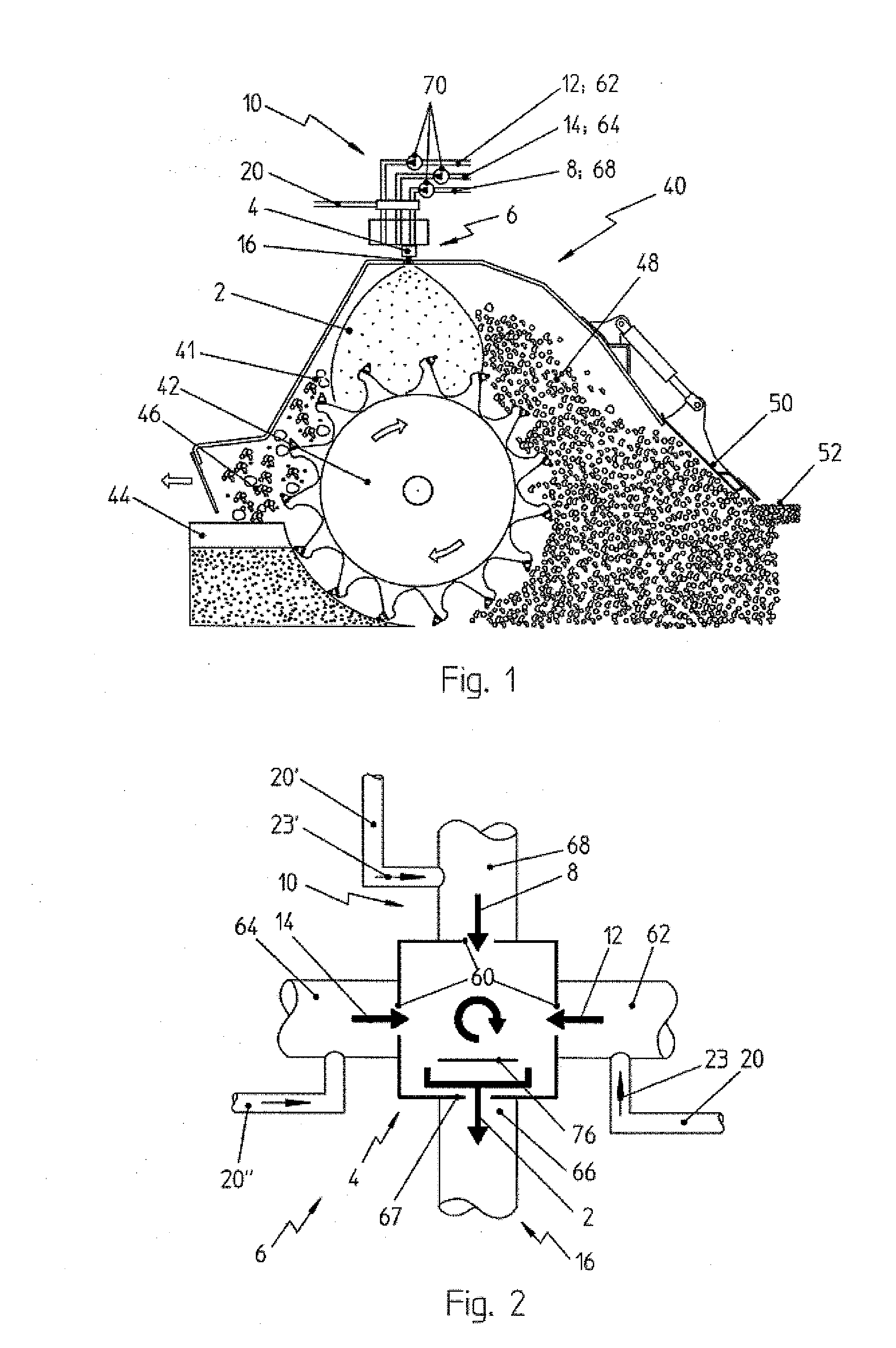
[0054]FIG. 1 shows a schematic view of a road construction machine and especially a recycling machine for upper road structures in road construction.

[0055]The illustrated road construction machine 40 comprises a milling wheel 42 in a rotation chamber 41, by means of which the existing road surface 44 can be milled off, the milled material can be crushed and processed into a new road surface 52. The milled raw material 46 is mixed for this purpose with the foamed bitumen 2, so that a bonded raw road material 48 is obtained which is applied by a smoothing apparatus 50 of the road construction machine 40 onto the base of the old road surface 44 and can be smoothed and compressed into a finished road support layer 52. The final road surface, especially an asphalt cover layer, can then be applied to the road supp...


PUM


Abstract

The present invention relates to an apparatus for producing foamed bitumen for a road construction machine, comprising at least one mixing device having a reaction chamber, in which hot bitumen and at least one reaction fluid can be mixed together via an inlet device comprising at least one inlet nozzle and can be discharged from the mixing device via an outlet device, with at least one compressed-air device being provided, via which the inlet device and / or the outlet device can be subjected to a compressed-air stream for testing and / or cleaning purposes. The present invention further also relates to a method for maintaining such an apparatus.

Description

CROSS-REFERENCE TO RELATED APPLICATIONS[0001]The present application is a Divisional application of U.S. Ser. No. 13 / 633,946, filed Jan. 2, 2013, which is a submission under 35 U.S.C. §371 of International Application No. PCT / EP2011 / 001710, filed Apr. 6, 2011, which claims priority to German Application No. 10 2010 013 982.3, filed Apr. 6, 2010, the disclosures of which are hereby expressly incorporated by reference herein in their entireties.FIELD OF THE INVENTION[0002]The present invention relates to an apparatus for producing foamed bitumen for a road construction machine, comprising at least one mixing device having a reaction chamber, in which hot bitumen and at least one reaction fluid can be mixed together via an inlet device comprising at least one inlet nozzle and can be discharged from the mixing device via an outlet device.[0003]The present invention further relates to a method for maintaining such an apparatus.BACKGROUND OF THE INVENTION[0004]Such apparatuses are require...

Claims


Application Information

Patent Timeline
Patent Type & Authority Applications(United States)
IPC IPC(8): E01C19/16B08B5/02E01C23/06B05B15/50B05B15/55
CPCE01C19/16B08B5/02E01C23/065C10C3/00E01C19/17B05B15/50B05B15/55B05B7/0025
Inventor HEUSINGER, JUERGENNACKE, ANDREASJORIG, THORSTEN
Owner BOMAG
Why Eureka
Try Eureka