Variable displacement swash plate compressor
a compressor and variable displacement technology, applied in the direction of positive displacement liquid engines, pump control, pump components, etc., can solve the problems of difficult displacement control, non-rotation movable body not being allowed to rotate about the rotation axis of the drive shaft, and difficult to provide open space in the housing at the second side of the swash plate, etc., to achieve the effect of superior displacement control
- Summary
- Abstract
- Description
- Claims
- Application Information
AI Technical Summary
Benefits of technology
Problems solved by technology
Method used
Image
Examples
first embodiment
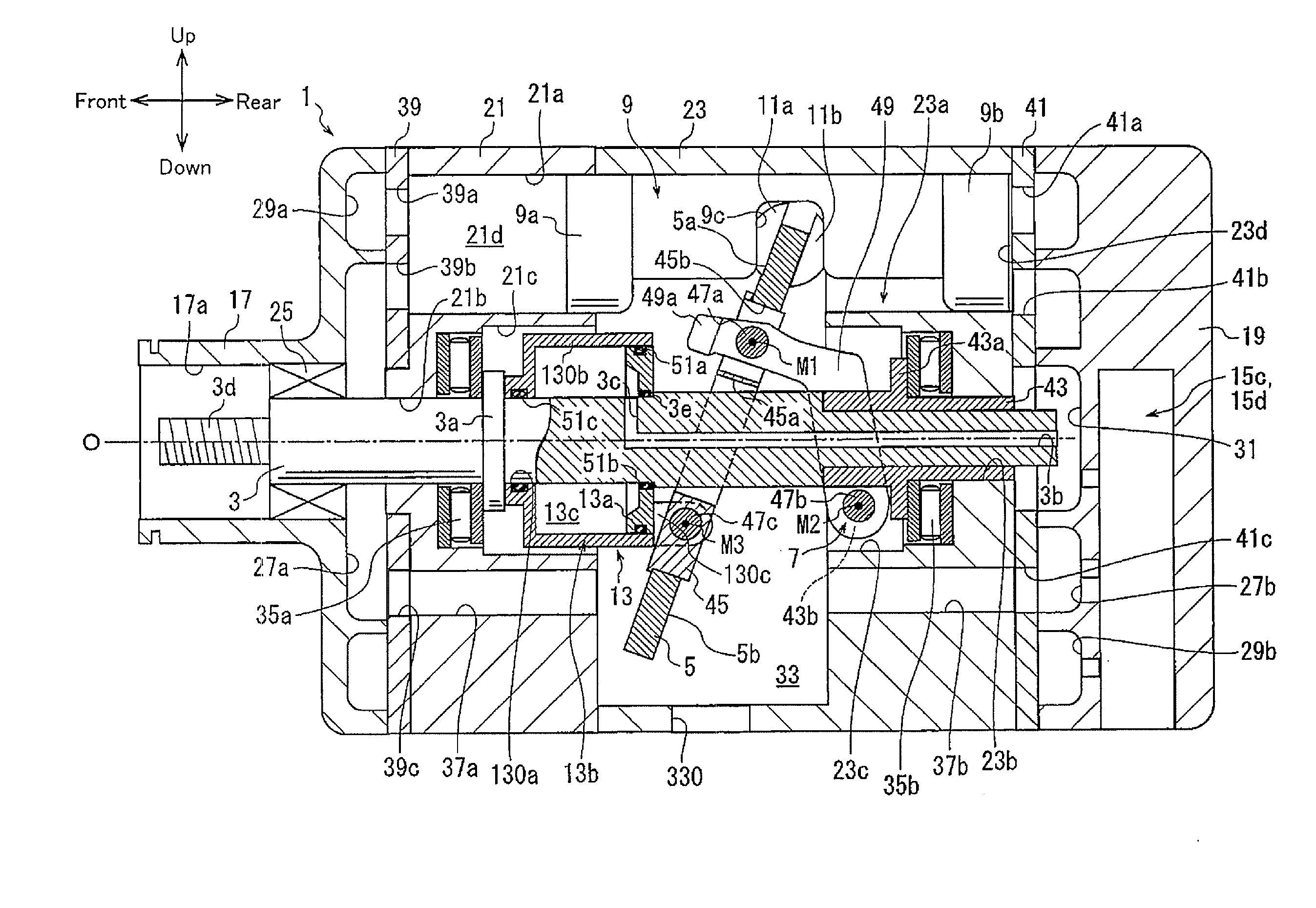
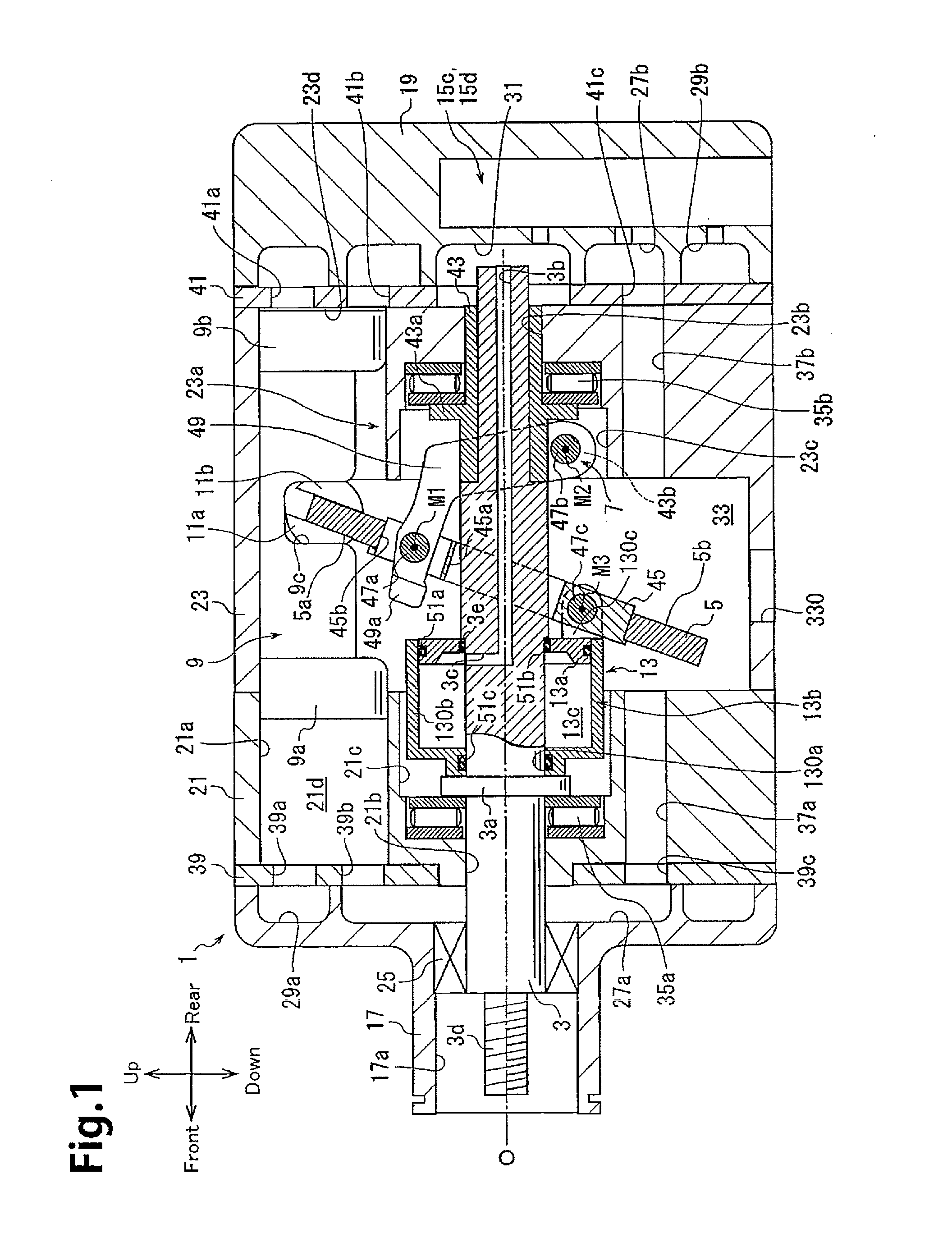
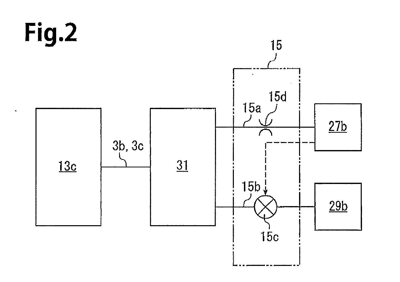
[0021]Referring to FIGS. 1 and 3, a compressor of the first embodiment includes a housing 1, a drive shaft 3, a swash plate 5, a link mechanism 7, pistons 9, front and rear shoes 11a and 11b, an actuator 13, and a control mechanism 15, which is shown in FIG. 2. Each piston 9 is provided with a pair of the shoes 11a and 11b.
[0022]As shown in FIG. 1, the housing 1 includes a front housing member 17, which is located at the front of the compressor, a rear housing member 19, which is located at the rear of the compressor, and first and second cylinder blocks 21 and 23, which are located between the front housing member 17 and the rear housing member 19.
[0023]The front housing member 17 includes a boss 17a, which projects toward the front. A sealing device 25 is arranged in the boss 17a around the drive shaft 3. Further, the front housing member 17 includes a first suction chamber 27a and a first discharge chamber 29a. The first suction chamber 27a is located in a radially inner portion...
second embodiment
[0073]A compressor of the second embodiment includes a control mechanism 16 shown in FIG. 4 in lieu of the control mechanism 15 used in the compressor of the first embodiment. The control mechanism 16 includes a bleed passage 16a, a gas supplying passage 16b, a control valve 16c, and an orifice 16d. The bleed passage 16a and the gas supplying passage 16b form a control passage.
[0074]The bleed passage 16a is connected to the pressure regulation chamber 31 and the second suction chamber 27b. Thus, the control pressure chamber 13c and the second suction chamber 27b are in communication with each other through the bleed passage 16a. The gas supplying passage 16b is connected to the pressure regulation chamber 31 and the second discharge chamber 29b. Thus, the control pressure chamber 13c and the pressure regulation chamber 31 are in communication with the second discharge chamber 29b through the gas supplying passage 16b. The gas supplying passage 16b includes the orifice 16d.
[0075]The...
PUM
 Abstract
Description
Claims
Application Information
 - R&D
- Intellectual Property
- Life Sciences
- Materials
- Tech Scout
- Unparalleled Data Quality
- Higher Quality Content
- 60% Fewer Hallucinations
Browse by: Latest US Patents, China's latest patents, Technical Efficacy Thesaurus, Application Domain, Technology Topic, Popular Technical Reports.
© 2025 PatSnap. All rights reserved.Legal|Privacy policy|Modern Slavery Act Transparency Statement|Sitemap|About US| Contact US: help@patsnap.com


