Image forming apparatus
- Summary
- Abstract
- Description
- Claims
- Application Information
AI Technical Summary
Benefits of technology
Problems solved by technology
Method used
Image

Examples
example 1
[0029]Example 1 will be described below.
[0030](General Configuration of Image Forming Apparatus)
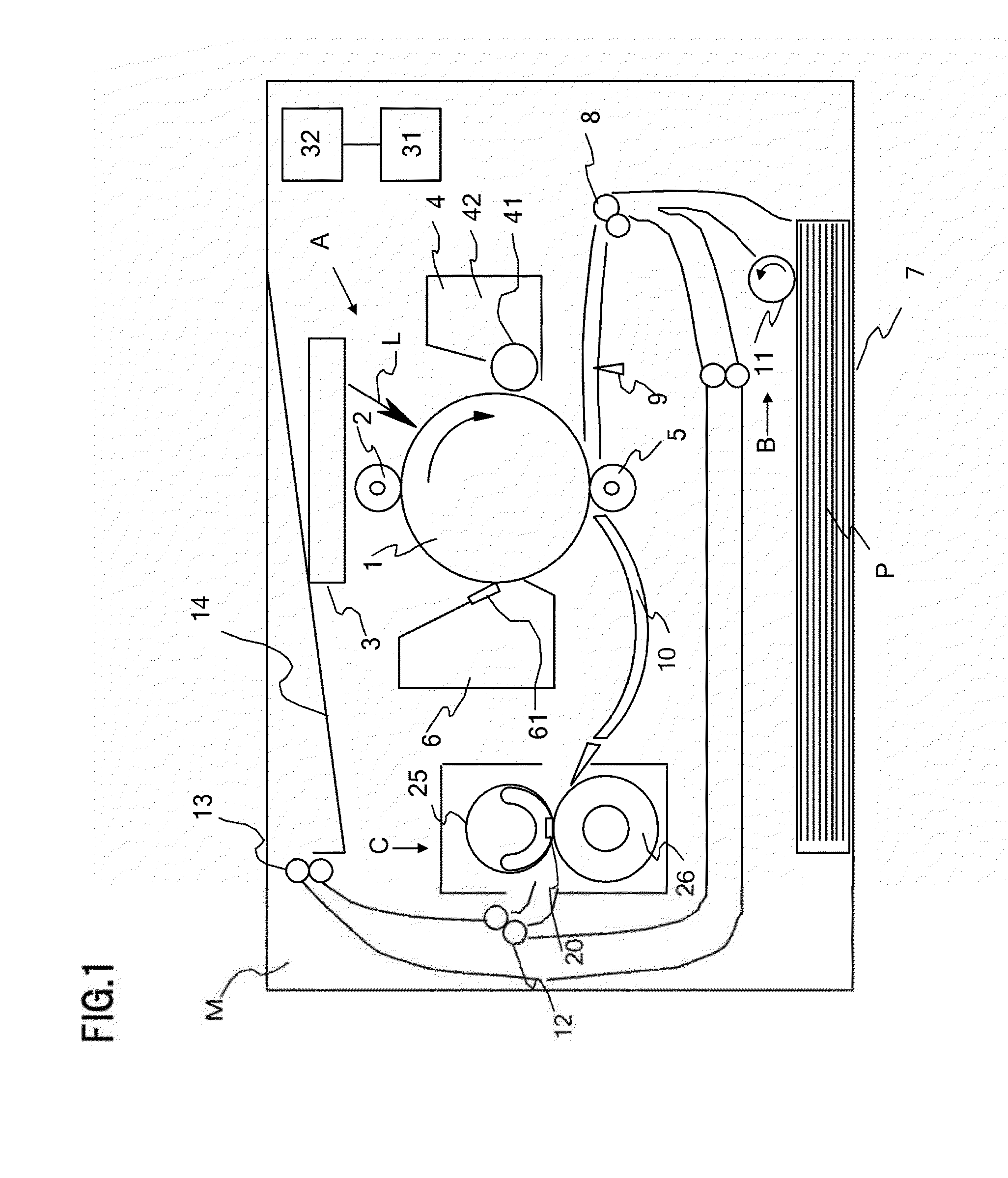
[0031]FIG. 1 is a cross-sectional view depicting a general configuration of an image forming apparatus according to this example.
[0032]The image forming apparatus of this example includes an image forming unit A that forms a toner image (toner image, developer image) on a recording material P, and a recording material feeding unit B that feeds the recording material P to the image forming unit A, and a fixing unit (hereafter called “fixing apparatus”) C that heats and fixes a toner image on the recording material P to the recording material P. Here the fixing apparatus C corresponds to an image heating unit.
[0033]The image forming unit A has a drum type electro-photographic photoreceptor (hereafter called “photosensitive drum”) 1, which functions as an image bearing member. The photosensitive drum 1 is rotatably supported by an image forming apparatus main unit (hereafter called “apparatu...
example 2
[0102]Example 2 will now be described. The differences of Example 2 from Example 1 are only in the configuration of the fixing apparatus and the sequence of the fixing control using the printing rate. In this example, only the composing elements that differ from Example 1 will be described, and description of the same composing elements as Example 1 is omitted.
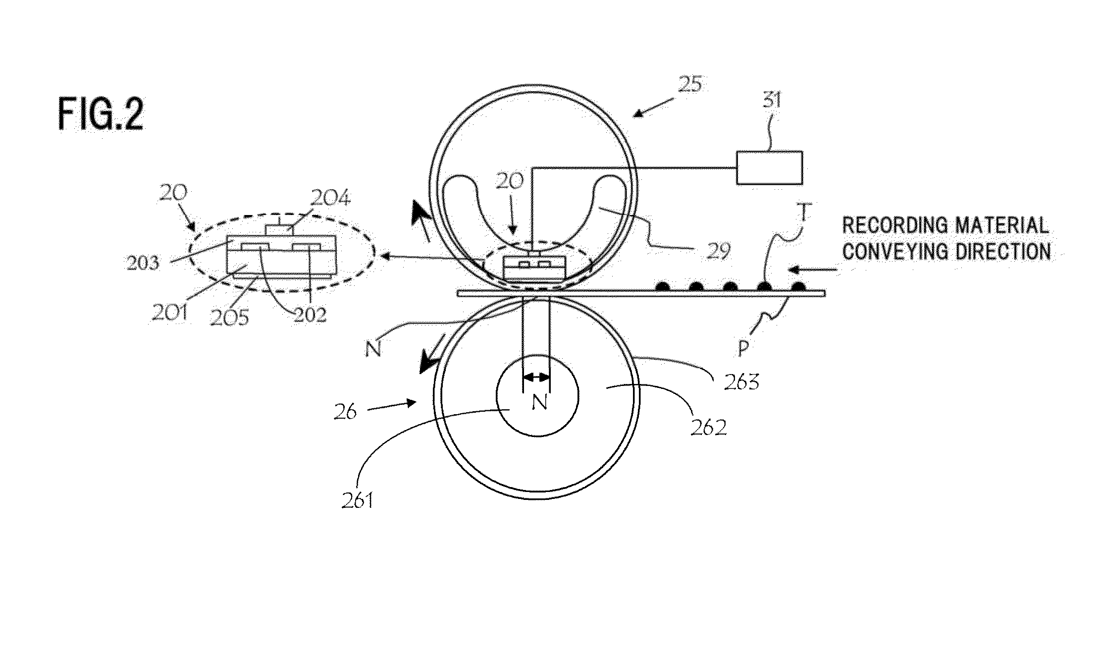
[0103]FIG. 9 is a cross-sectional view depicting a general configuration of a fixing apparatus C of this example. The configuration of this example is suitable for an image forming apparatus of which the thermal conductivity of the heater substrate 201 in the longitudinal direction is low, and temperature rising in the non-paper passing portions is conspicuous.
[0104](Configuration of Fixing Apparatus)
[0105]In the fixing apparatus C of this example, composing elements that differ from Example 1 are: a heater 20 and a fixing film 25. The configuration of the fixing apparatus C of this example will be described with reference to ...
example 3
[0122]Example 3 will now be described. The differences of Example 3 from Example 1 are only in the configuration of the fixing apparatus and the sequence of the fixing control using the information on the printing rate. In this example, only the composing elements that differ from Example 1 will be described, and description of the same composing elements as Example 1 is omitted.
[0123]FIG. 13 is a cross-sectional view depicting a general configuration of a heater 20 of this example. The configuration of this example is suitable for an image forming apparatus of which longitudinal thermal conductivity of the heater 20 is enhanced, whereby the temperature rising in the non-paper passing portions is decreased.
[0124](Configuration of Fixing Apparatus)
[0125]The configuration of the fixing apparatus C of this example will be described with reference to FIG. 13. A high thermal conductivity plate 209, as the high thermal conductivity member, is contacted to the heater 20 of this example, so...
PUM
 Abstract
Description
Claims
Application Information
 - R&D Engineer
- R&D Manager
- IP Professional
- Industry Leading Data Capabilities
- Powerful AI technology
- Patent DNA Extraction
Browse by: Latest US Patents, China's latest patents, Technical Efficacy Thesaurus, Application Domain, Technology Topic.
© 2024 PatSnap. All rights reserved.Legal|Privacy policy|Modern Slavery Act Transparency Statement|Sitemap