
Cable connector assembly installed conveniently and method of assembling the same

a technology of cable connectors and connector assemblies, which is applied in the direction of contact member assemblies/disassemblies, coupling device connections, electric discharge lamps, etc., can solve the problem of low stability of the insulative body

Active Publication Date: 2015-10-01
FOXCONN INTERCONNECT TECHNOLOGY LIMITED
View PDF9 Cites 0 Cited by
  • Summary
  • Abstract
  • Description
  • Claims
  • Application Information

AI Technical Summary

Benefits of technology

The invention relates to a design for a plastic housing that has a through hole filled with adhesive. The adhesive provides enough holding power to secure the housing in place. Excess adhesive is collected in a receiving slot to prevent it from flowing out of the housing. The technical effect of this design is that it provides a secure and reliable attachment of the plastic housing to other components, which can withstand high levels of stress and impact.

Problems solved by technology

Since the plastic case is molded to enclose the metal shell, stability of the insulative body is low.

Method used


Image

  • Cable connector assembly installed conveniently and method of assembling the same
  • Cable connector assembly installed conveniently and method of assembling the same
  • Cable connector assembly installed conveniently and method of assembling the same

Examples


Embodiment Construction

[0014]Reference will now be made in detail to some preferred embodiments of the present invention.

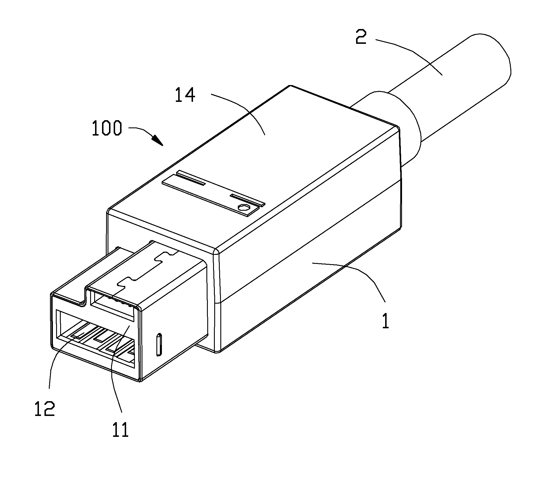
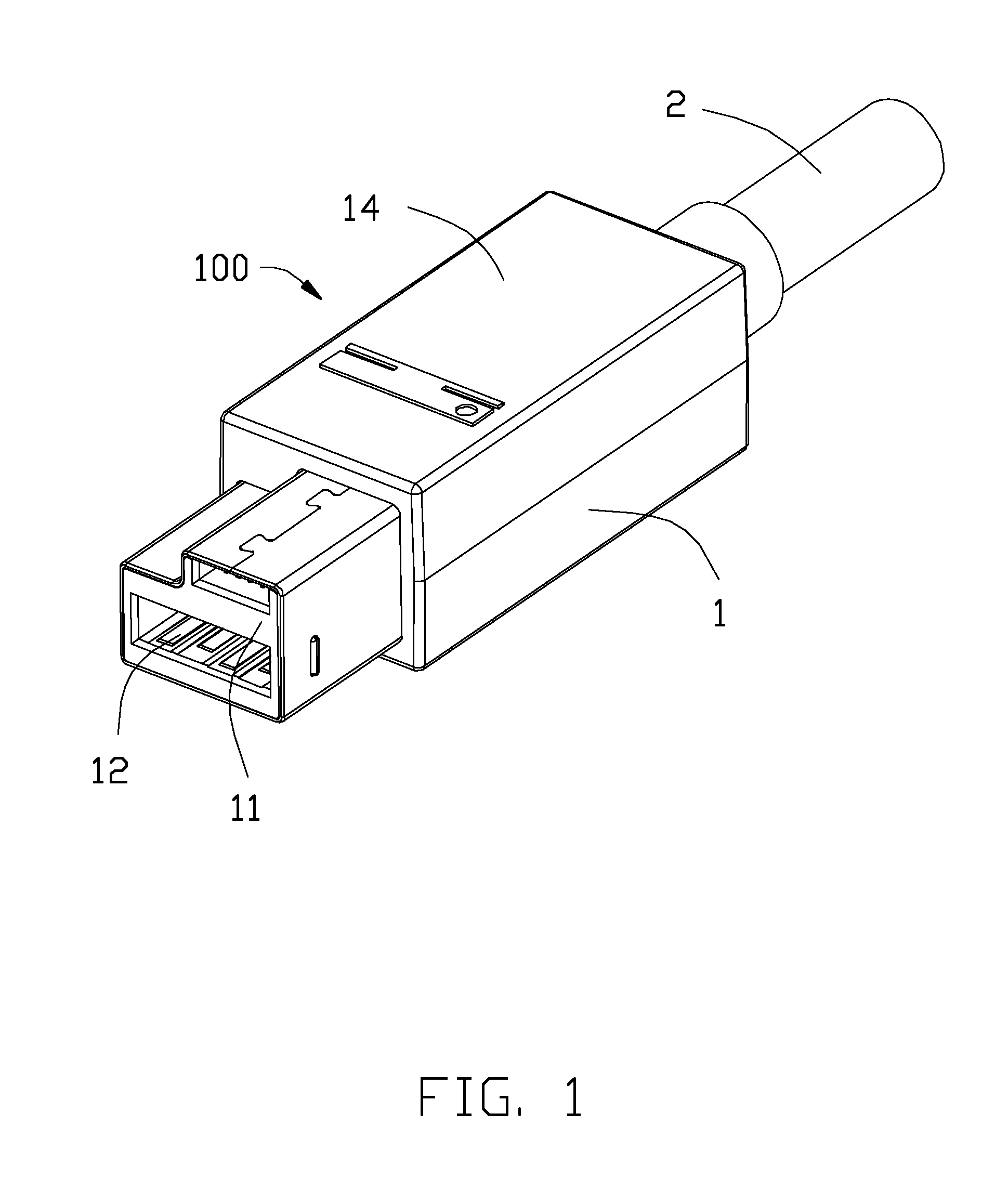
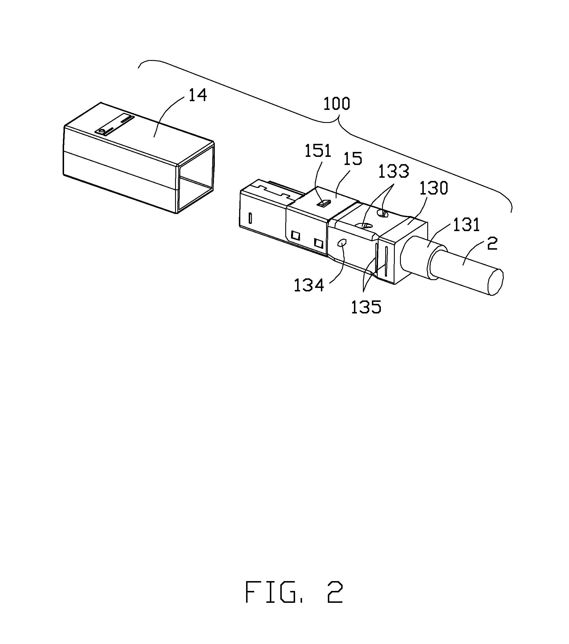
[0015]Referring to FIGS. 1 to 4, a cable connector assembly 100 comprises a cable connector 1 and a cable 2 connected to the cable connector 1. The cable connector 1 comprises an insulative body 11, a plurality of terminals 12 held in the insulative body 11, an internal member 13 molded in the cable connector 1 and the cable 2, a plastic housing 14 disposed out of the internal member 13, and a metal shell 15 disposed in the plastic housing 14.

[0016]Referring to FIG. 5, the internal member 13 comprises a main portion 130 and an annular portion 131 set on the cable 2. The main portion 130 comprises a through hole 132 penetrating obliquely the internal member 13. The through hole 132 forms a first opening 133 proximal to the cable 2 and a second opening 134 distal from the cable 2 on the internal member 13. When the plastic housing 14 is mounted to cover the second opening 134 but not the ...


PUM

PropertyMeasurementUnit
sizeaaaaaaaaaa
stabilityaaaaaaaaaa
holding forceaaaaaaaaaa

Abstract

A cable connector assembly and method of assembling the same. The cable connector assembly includes a cable connector and a cable connected to the cable connector. The cable connector includes an insulative body, a plurality of terminals held in the insulative body, an internal member molded in the cable connector, and a plastic housing disposed outside of the internal member. The internal member includes a through hole penetrating obliquely the internal member. The through hole includes a first opening proximal to the cable and a second opening distal from the cable. Adhesive is filled the through hole from the first opening through the second opening to contact with an inner surface of the plastic housing.

Description

BACKGROUND OF THE INVENTION[0001]1. Field of the Invention[0002]The present invention relates to a cable connector assembly, and more particularly to a fixing structure of plastic housing of the cable connector assembly, as well as to a manufacturing method of such cable connector assembly.[0003]2. Description of Related Arts[0004]U.S. Pat. No. 8,100,725, issued on Jan. 24, 2012, discloses a cable connector assembly including an insulative body, a number of terminals, a spacer assembled to the insulative body, a cable electrically connecting to the terminals, a metal shell enclosing the insulative body for EMI protection, and a plastic case surrounding the metal shell and a front portion of the cable. Since the plastic case is molded to enclose the metal shell, stability of the insulative body is low.[0005]An improved cable connector assembly is desired to offer advantages over the related art.SUMMARY OF THE INVENTION[0006]An object of the present invention is to provide a cable con...

Claims


Application Information

Patent Timeline
Patent Type & Authority Applications(United States)
IPC IPC(8): H01R13/516H01R13/405H01R24/30
CPCH01R13/516H01R13/405H01R24/30H01R13/46H01R13/514H01R43/00H01R43/20H01R13/504
Inventor WU, JERRYCHEN, JUNMENG, FAN-BO
Owner FOXCONN INTERCONNECT TECHNOLOGY LIMITED
Learn More