Electromechanical brake pressure generator for a hydraulic braking system of a vehicle and vehicle including an electromechanical brake pressure generator

a technology of electromechanical brake and generator, which is applied in the direction of brake cylinder, vehicle sub-unit features, and gearing, etc., can solve the problems of insufficient foot force of the driver for braking motor vehicles, and achieve the effect of easy installation, easy and economical production, and sufficient holding for

Active Publication Date: 2020-10-29
ROBERT BOSCH GMBH
View PDF0 Cites 4 Cited by
  • Summary
  • Abstract
  • Description
  • Claims
  • Application Information

AI Technical Summary

Benefits of technology

[0020]The recesses are preferably situated on the side of the spindle nut. As a result, no parts protrude from the spindle nut, so that components, such as a bearing, may be installed more easily prior to the assembly of the drive wheel. The recess areas are, in particular, smaller than the areas situated between the recesses. In this way, in particular, a sufficient holding force of the areas situated between the recesses may be ensured.
[0021]In one advantageous refinement, the protrusions have a rectangular cross section. In the case of the rectangular cross section, the protrusions have a constant thickness across the length. In this way, it is possible to create the protrusions without making undercuts necessary. This allows such protrusions to be created easily and economically.

Problems solved by technology

The foot force of the driver is mostly not sufficient for braking motor vehicles, so that these are usually equipped with a brake booster.
Alternative brake pressure buildup devices are needed for future drive concepts of motor vehicles since a vacuum is no longer available to operate a conventional vacuum brake booster.

Method used


Image

  • Electromechanical brake pressure generator for a hydraulic braking system of a vehicle and vehicle including an electromechanical brake pressure generator
  • Electromechanical brake pressure generator for a hydraulic braking system of a vehicle and vehicle including an electromechanical brake pressure generator
  • Electromechanical brake pressure generator for a hydraulic braking system of a vehicle and vehicle including an electromechanical brake pressure generator

Examples


Embodiment Construction

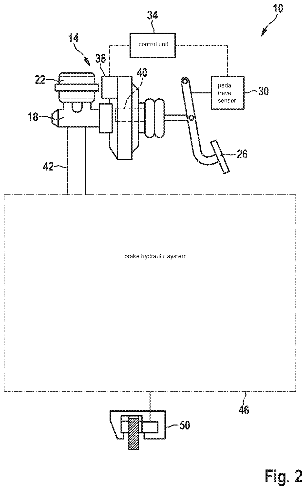
[0030]FIG. 2 shows a schematic illustration of a hydraulic braking system 10 for a vehicle including an electromechanical brake pressure generator 14. Hydraulic braking system 10 includes electromechanical brake pressure generator 14. This brake pressure generator 14 includes a piston / cylinder unit 18 which is supplied with brake fluid via a brake fluid reservoir 22.

[0031]Piston / cylinder unit 18 may be activated by a brake pedal 26 actuated by the driver, and the resulting brake pedal travel is measured by a pedal travel sensor 30 and forwarded to a control unit 34. Even though FIG. 2, in principle, shows a brake booster, it is essential here that the brake pedal travel is measured by pedal travel sensor 30. A brake pressure generation without a brake pedal travel is also possible, so that the vehicle is also brakable in the autonomous driving state.

[0032]Based on the measured brake pedal travel, control unit 34 generates a control signal for an electric motor 38 of brake pressure g...


PUM


Abstract

An electromechanical brake pressure generator for a hydraulic braking system of a vehicle. The electromechanical brake pressure generator includes at least one threaded drive system for converting a drive-side rotary motion into a translatory motion for the brake pressure generation. The threaded drive system includes a rotatable spindle nut, and a spindle cooperating with a thread of the spindle nut so that the spindle is axially displaceable with a rotation of the spindle nut. The threaded drive system includes a drive wheel, which is non-rotatably situated on the spindle nut and via which the spindle nut is connected to the electric motor, the drive wheel and the spindle nut being designed as separate plastic components, including a plurality of mutually corresponding connecting structures which, in the assembled state, engage one another in a form-locked manner in such a way that a torque required for rotating the spindle nut is transmittable.

Description

CROSS REFERENCE[0001]The present application claims the benefit under 35 U.S.C. § 119 of German Patent Application No. DE 102019205972.4 filed on Apr. 25, 2019, which is expressly incorporated herein by reference.FIELD[0002]The present invention relates to an electromechanical brake pressure generator for a hydraulic braking system of a vehicle and to a vehicle including an electromechanical brake pressure generator.[0003]The electromechanical brake pressure generator includes, in particular, a threaded drive system for converting a drive-side rotary motion into a translatory motion for the brake pressure generation.BACKGROUND INFORMATION[0004]The foot force of the driver is mostly not sufficient for braking motor vehicles, so that these are usually equipped with a brake booster. Conventional brake boosters in general operate with the aid of a vacuum generated by the internal combustion engine. The pressure difference between the engine pressure and the ambient pressure is used in t...

Claims


Application Information

Patent Timeline
Patent Type & Authority Applications(United States)
IPC IPC(8): B60T13/74B60T13/16B60T17/08F16H25/20
CPCB60T13/161B60T17/08F16H2025/2081F16H25/20B60T13/745F16H2025/2046B60T13/746B60T13/66B60T13/12B60T7/042F16D2125/40F16H2025/249F16H25/24F16H55/06B60Y2400/81
Inventor BOEHM, MARKOEHLER, CLAUS
Owner ROBERT BOSCH GMBH
Why Eureka
Try Eureka