Spacer clip

A technology of clamping position and legs, which is applied in the field of spacer clips, can solve problems such as difficult bending of locking claws

Active Publication Date: 2010-06-30
NEWFREY
View PDF3 Cites 9 Cited by
  • Summary
  • Abstract
  • Description
  • Claims
  • Application Information

AI Technical Summary

Problems solved by technology

[0006] However, the spacer in Patent Document 1 has a structure that makes it difficult to bend the locking claws on the side of the flange.

Method used


Image

  • Spacer clip
  • Spacer clip
  • Spacer clip

Examples


Embodiment Construction

[0050] Preferred Embodiments of the Invention

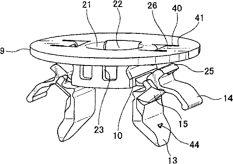
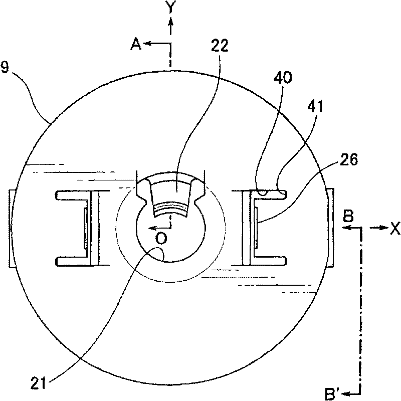
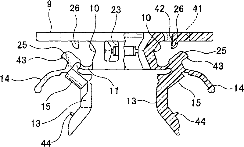
[0051] Examples of the present invention will now be described with reference to schematic diagrams. exist Figure 1 to Figure 3 In , a spacer clip 1 relating to an embodiment of the present invention is shown. Figure 4 Another situation is shown in which the spacer clip 1 is connected to a sheet-like part 2, such as a part of sound-insulating material being connected. Figure 6 Another situation is shown in which a sheet member 2 to which a spacer clip 1 has been coupled is fixed into a member such as a vehicle body 3 by means of bolts 5 and nuts 6 . spacer clip 1, such as Figure 4As shown, it is fixed to the flexible sheet member 2 having a through hole by passing through the through hole 7 and clamping the sheet member 2 from both sides. Even when the sheet member 2 is a soft material connecting member such as a sound-proof material, the spacer clip 1 can connect the sheet member 2 to another member such as the vehicle b...


PUM


Abstract

A spacer clip including a flange, a shank extending from the flange that can be inserted into a through in a member being attached to, legs extending from the end part of the shank, connected by hinges to the shank end part so as that they can pivot from an initial attitude to a clamping attitude wherein they are substantially parallel to the flange. Levers extend from root portions of the legs toward the tip ends of the legs so that they can pivot together with the legs. The legs have leg-side pawls in the portions thereof adjacent to the shank end part, which extend to the flange side when the legs are in the clamping attitude, the flange has flange-side pawls for engaging the leg-side pawls and maintaining the legs in the clamping attitude, and slits are formed on either side of the flange-side pawls.

Description

technical field [0001] The present invention relates to a spacer clip for connecting to a part to be connected such as a soft sheet part having a through hole therein, and more particularly to a spacer clip which passes through the through hole and clamped from both sides to enable fixing to sheet material such as soundproofing material and to enable the sheet member to be attached to other components such as panels. Background technique [0002] A number of clips are known for attaching soft sheet materials such as cushions or sound deadening materials to car bodies or the like. The clip is fastened to the sheet material, and the clip is then fastened to a threaded bolt which has been fastened to a car body or the like, thus effecting the connection of the sheet parts. [0003] Patent Document 1 filed by the present applicant provides a spacer clip which can be connected to a connected member such as a sheet member by an operation of pressing it in from one side. [0004]...

Claims


Application Information

Patent Timeline
Patent Type & Authority Applications(China)
IPC IPC(8): F16B5/06
CPCF16B5/065F16B5/02B60R13/0206Y10T24/309Y10T24/44026Y10T24/44274Y10T24/45105
Inventor 柴大辅
Owner NEWFREY
Why Eureka
Try Eureka