
Electrical connector

a technology of electrical connectors and connectors, applied in the direction of electrical apparatus, connection, coupling device connection, etc., can solve the problems of dropping out of the preassembled position or even being los

Active Publication Date: 2021-07-08
ALLTOP ELECTRONICS SU ZHOU
View PDF0 Cites 0 Cited by
  • Summary
  • Abstract
  • Description
  • Claims
  • Application Information

AI Technical Summary

Benefits of technology

The present invention provides an electrical connector that can be easily assembled and has a sufficient contact holding force. The retainer and contacts of the connector can be easily assembled, and the retainer is less likely to be lost during transport. The contacts are better able to make contact with complementary contacts, resulting in improved performance.

Problems solved by technology

A common retainer generally has two states: preassembled in the insulative housing and detached from the insulative housing, however, the retainer may be pushed by mistake before the contacts inserted into the insulative housing, and may drop out of the preassembled position or even be lost, on the other hand, an additional tool is needed to push the retainer into the insulative housing.

Method used


Image

  • Electrical connector
  • Electrical connector
  • Electrical connector

Examples


Embodiment Construction

[0029]Reference will be made to the drawing figures to describe the present invention in detail, wherein depicted elements are not necessarily shown to scale and wherein like of similar elements are designated by same or similar reference numeral through the several views and same or similar terminology.

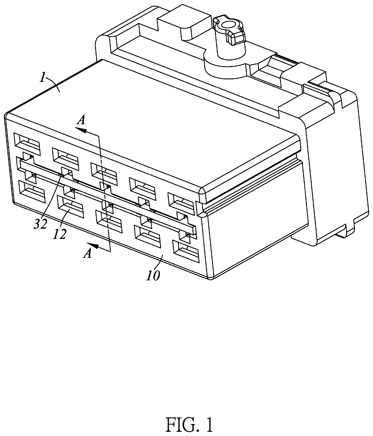
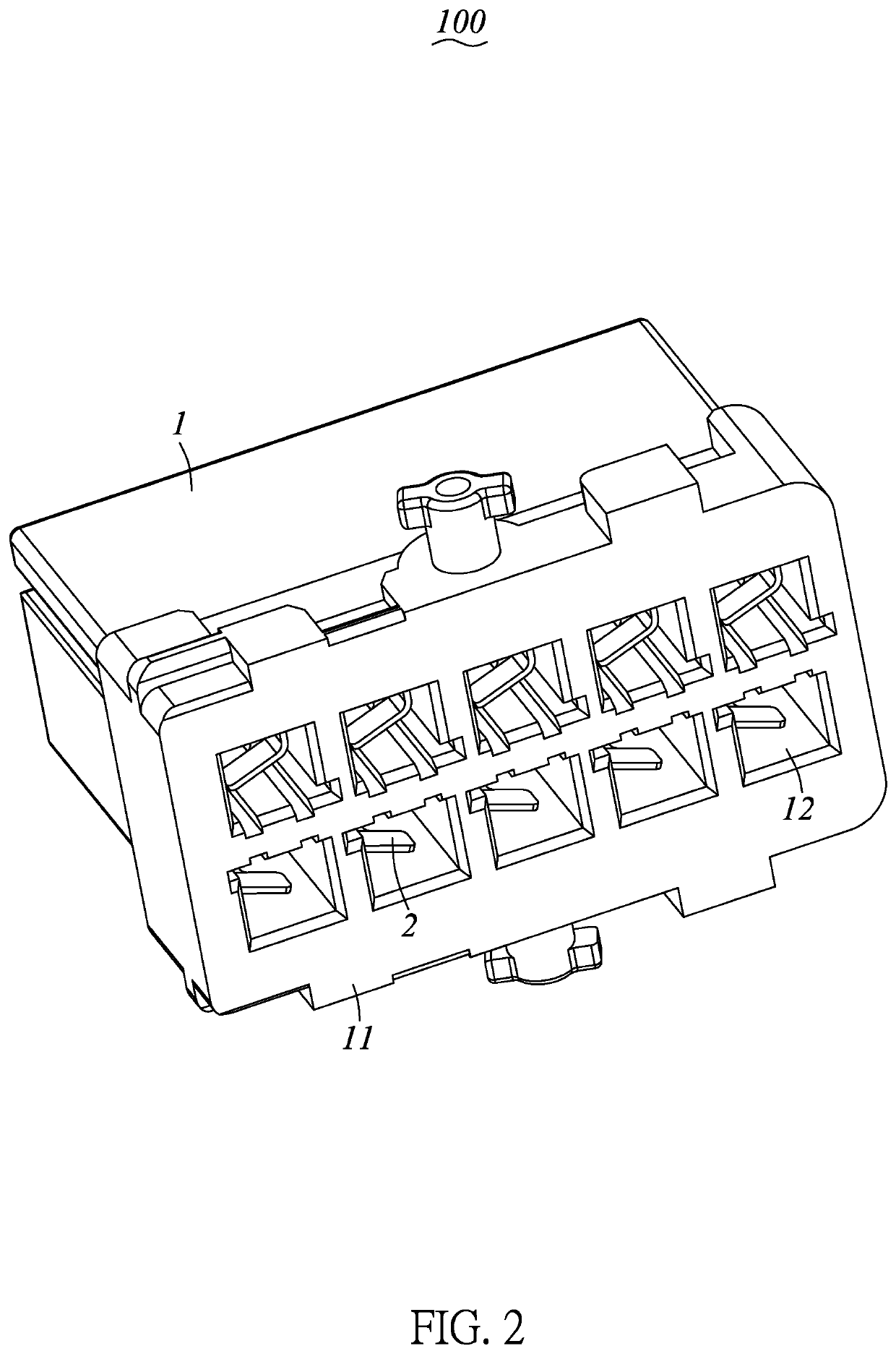
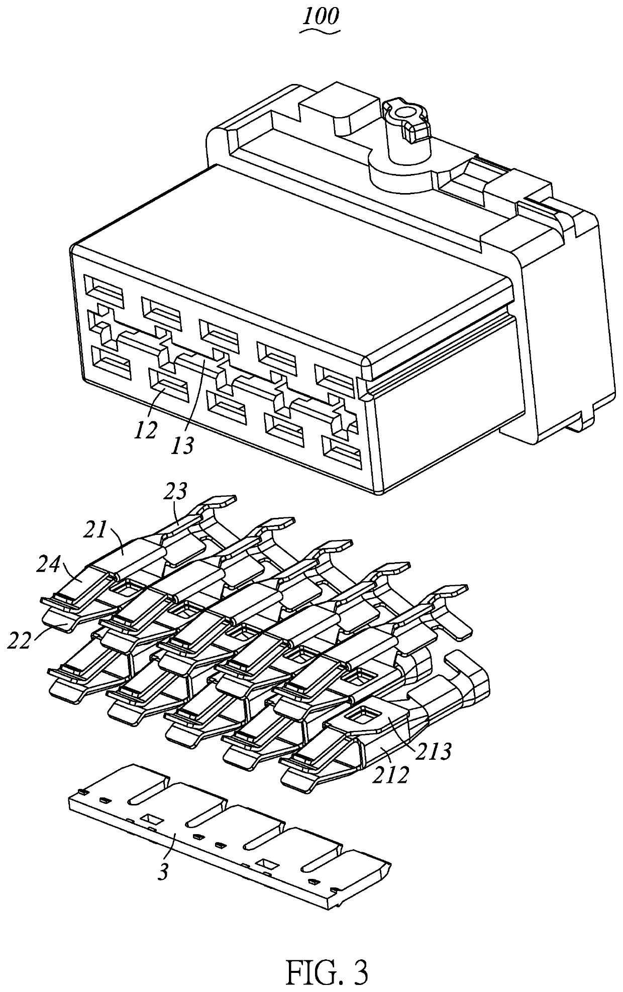
[0030]Please refer to FIG. 1 to FIG. 11, showing an electrical connector 100 in present invention, the electrical connector 100 comprises an insulative housing 1, a plurality of contacts 2 retained in the insulative housing 1 and a retainer 3 assembled to the insulative housing 1.

[0031]Referring to FIG. 1 to FIG. 4, and combination with FIG. 7 to FIG. 11, the insulative housing 1 has a mating face 10 and a mounting face 11 opposite to each other, and comprises a plurality of passageways 12 passing through thereof along a front-and-back direction and a receiving cavity 13 recessed backwards from the mating face 10.

[0032]In the present embodiment of the invention, two rows of the passa...


PUM


Abstract

An electrical connector comprising an insulative housing and a retainer assembled into the insulative housing. The insulative housing has a mating face and a mounting face opposite to each other, and comprises a plurality of passageways passing through thereof along a front-and-back direction for receiving corresponding contacts and a receiving cavity recessed backwards from the mating face. The retainer is provided with a plurality of first latching portions and a plurality of second latching portions, and the first latching portions and the second latching portions are staggered along the front-and-back direction, the retainer is assembled and locked in the insulative housing without dropping out of the insulative housing via the first latching portions; after the contacts assembled into the insulative housing, the retainer is pushed towards the mounting face by an external force, until the second latching portions locked in receiving cavity.

Description

CROSS REFERENCE OF THE RELATED APPLICATIONS[0001]This application claims priority of the Chinese patent application No. 201710860285.X, filed on Sep. 21, 2017 and with the title of “electrical connector”, which is incorporated herein by reference in its entirety.FIELD OF THE INVENTION[0002]The present invention relates to an electrical connector, and more particularly to an electrical connector with convenient assembly and better retention force.BACKGROUND OF THE INVENTION[0003]A conventional electrical connector used in automobile industry, usually includes an insulative housing, a plurality of contacts and a retainer. The retainer is used for locking the contacts and enhancing the retaining force of the contact in the insulative housing. A common retainer generally has two states: preassembled in the insulative housing and detached from the insulative housing, however, the retainer may be pushed by mistake before the contacts inserted into the insulative housing, and may drop out ...

Claims


Application Information

Patent Timeline
Patent Type & Authority Applications(United States)
IPC IPC(8): H01R13/436H01R13/422
CPCH01R13/4368H01R13/4223H01R13/4365
Inventor CHENG, IHUNGDAI, QIQINGYANG, SIUMIENYU, WANGI
Owner ALLTOP ELECTRONICS SU ZHOU
Learn More