
Apparatus and method for analyzing trajectory

a trajectory and apparatus technology, applied in the field of computer vision, can solve the problems of reducing tracking accuracy, difficult to improve tracking accuracy, and may not reach a predetermined level

Active Publication Date: 2015-10-08
PANASONIC CORP
View PDF3 Cites 10 Cited by
  • Summary
  • Abstract
  • Description
  • Claims
  • Application Information

AI Technical Summary

Benefits of technology

The patent places a high value on information that is outputted during a moving-objects tracking process, even if the tracking accuracy is low. This means that even if the tracking is not very precise, the system will still output important information based on the data it receives during the tracking process.

Problems solved by technology

Such a moving-object tracking process allows for tracking of the moving object with high accuracy; however, this process causes accumulation of errors and tends to reduce the tracking accuracy as the moving object moves away from the start point of the trajectory thereof.
However, even when the moving-object tracking algorithm is changed to another, the tracking accuracy may not reach a predetermined level.
For example, for a moving object which moves very fast or freely or moving object which largely changes in appearance, the tracking accuracy is difficult to improve.

Method used


Image

  • Apparatus and method for analyzing trajectory
  • Apparatus and method for analyzing trajectory
  • Apparatus and method for analyzing trajectory

Examples


first embodiment

[0031]A first embodiment of the present disclosure is an example of the basic aspect of the present disclosure.

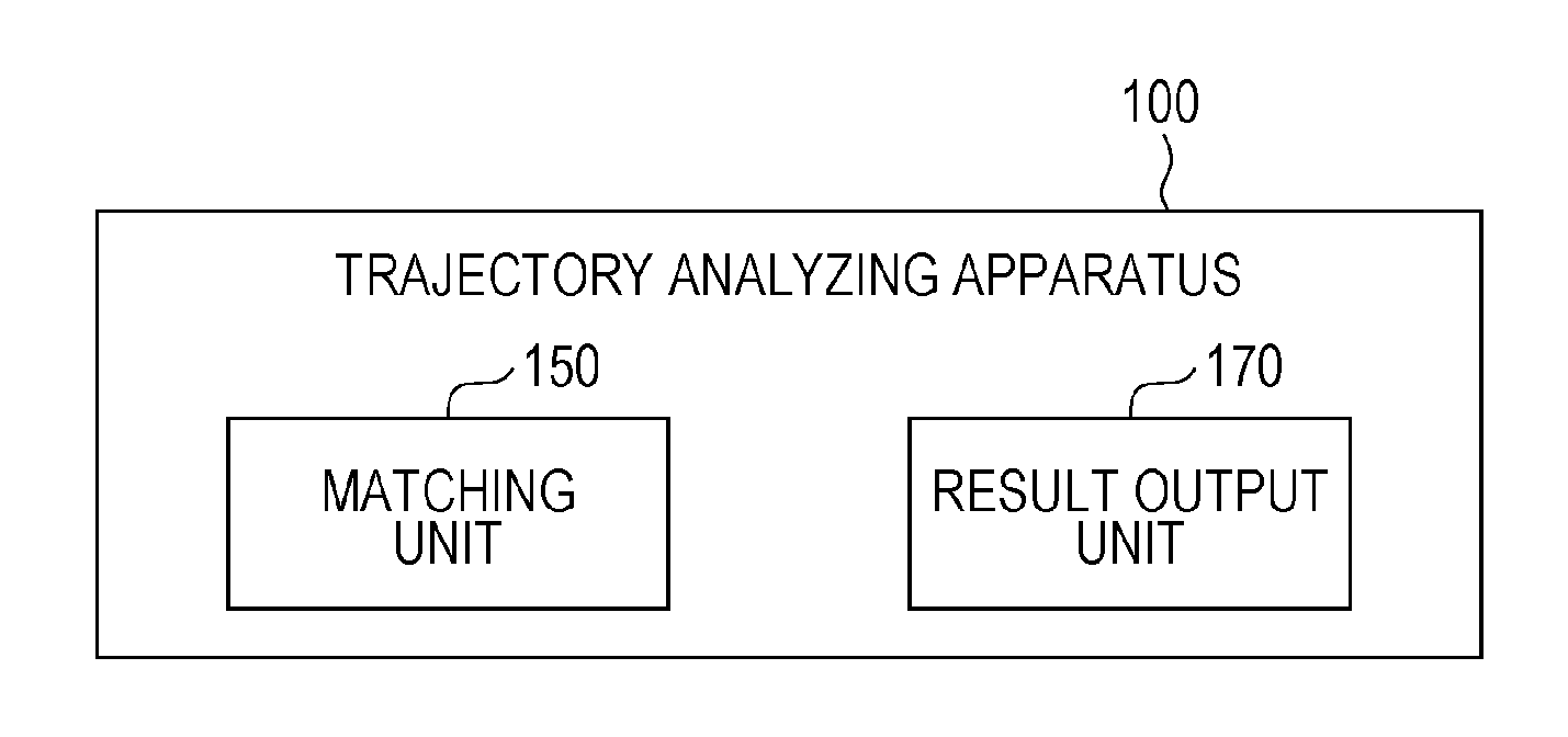
[0032]FIG. 1 is a block diagram showing the configuration of a trajectory analyzing apparatus according to the present embodiment.

[0033]In FIG. 1, a trajectory analyzing apparatus 100 includes a matching unit 150 and a result output unit 170.

[0034]The matching unit 150 calculates the correlation between a forward trajectory obtained by tracking a moving object over pictures along the forward direction of the time axis and a backward trajectory obtained by tracking a moving object over the pictures along the backward direction of the time axis.

[0035]The result output unit 170 outputs trajectory information indicating at least one of the forward trajectory, the backward trajectory, and an integrated trajectory obtained by integrating these trajectories and indicating the reliability of the at least one trajectory based on the calculated correlation.

[0036]Although not shown, t...

second embodiment

[0038]A second embodiment of the present disclosure is one specific aspect of an apparatus which analyzes results obtained by tracking multiple moving objects and to which the present disclosure is applied.

Configuration of Trajectory Analyzing Apparatus

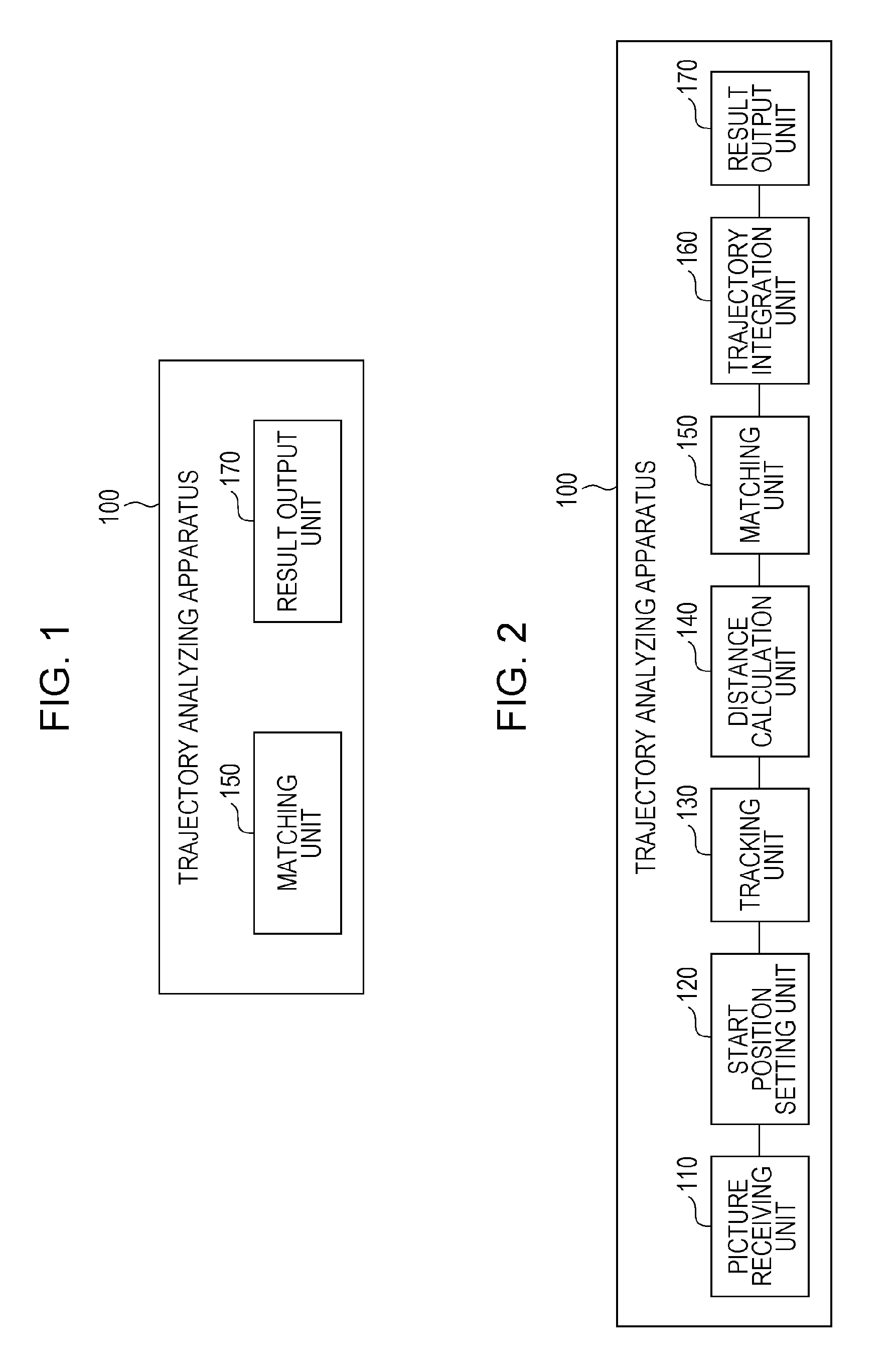
[0039]FIG. 2 is a block diagram showing an example of the configuration of a trajectory analyzing apparatus according to the present embodiment.

[0040]In FIG. 2, the trajectory analyzing apparatus 100 includes a picture receiving unit 110, a start position setting unit 120, a tracking unit 130, a distance calculation unit 140, a matching unit 150, a trajectory integration unit 160, and a result output unit 170.

[0041]The picture receiving unit 110 receives a predetermined length of picture data including time-series frames (hereafter simply referred to as “pictures”). The picture receiving unit 110 may receive pictures directly from a digital camera, may read pictures from a storage medium, or may receive pictures from a server on a net...


PUM


Abstract

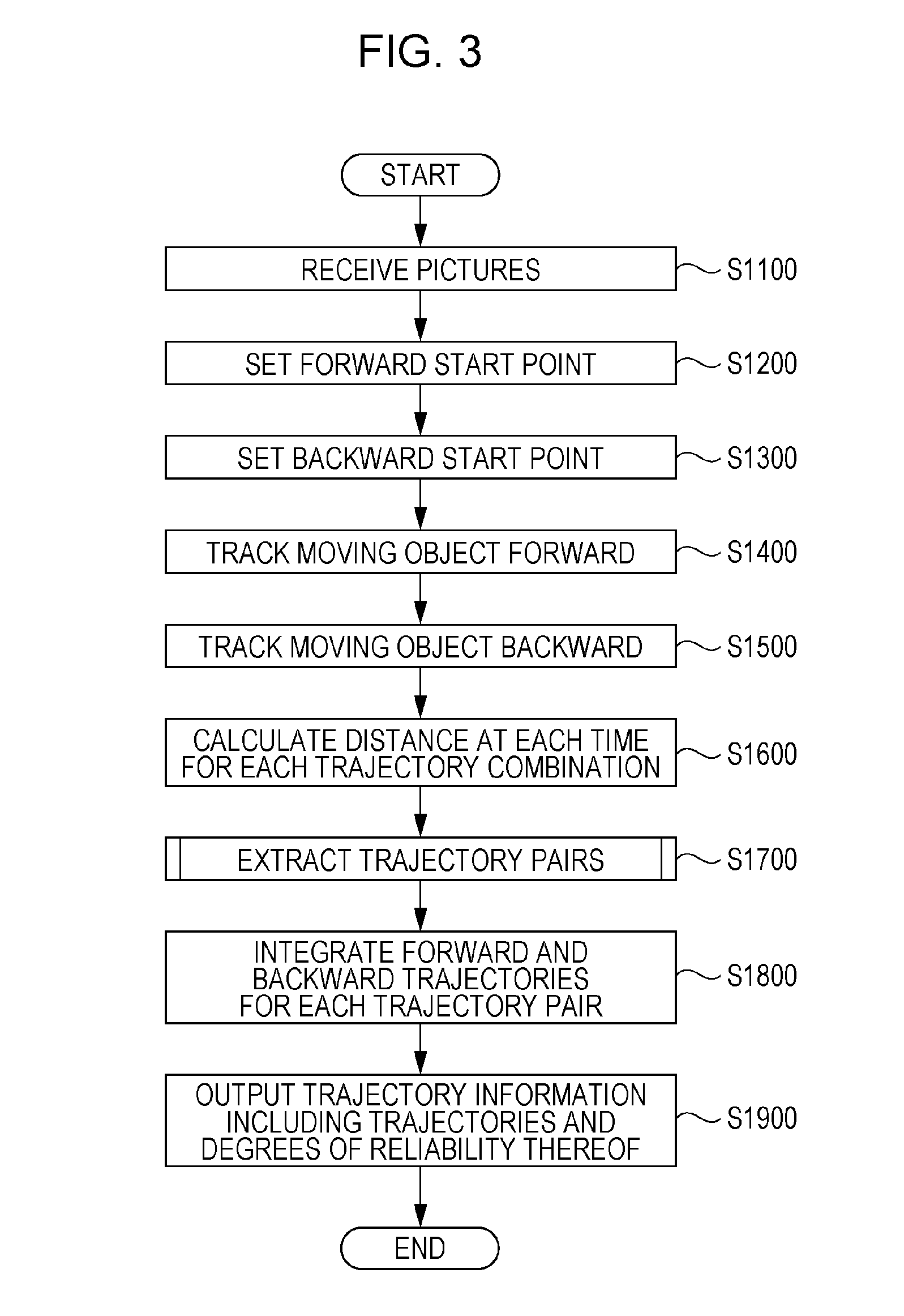
A trajectory analyzing apparatus includes a matching unit that calculates the correlation between a forward trajectory obtained by tracking a moving object over pictures along the forward direction of the time axis and a backward trajectory obtained by tracking a moving object over the pictures along the backward direction of the time axis and a result output unit that outputs trajectory information indicating at least one of the forward trajectory, the backward trajectory, and an integrated trajectory obtained by integrating the forward trajectory and backward trajectory and indicating the degree of reliability of the at least one trajectory based on the calculated correlation.

Description

BACKGROUND[0001]1. Technical Field[0002]The present disclosure relates to a computer vision and in particular to a trajectory analyzing apparatus and method that analyze a result obtained by tracking a moving object over pictures.[0003]2. Description of the Related Art[0004]A process of tracking the movement of a moving object over pictures by extracting the moving object from time-series frames forming the pictures (hereafter referred to as the “moving-object tracking process”) have been utilized in various fields in recent years.[0005]In the moving-object tracking process, typically, the image features and position of a moving object extracted from the preceding and earlier frames are used to search for the moving object in the subsequent frame. Such a moving-object tracking process allows for tracking of the moving object with high accuracy; however, this process causes accumulation of errors and tends to reduce the tracking accuracy as the moving object moves away from the start...

Claims


Application Information

Patent Timeline
Patent Type & Authority Applications(United States)
IPC IPC(8): G06K9/00G06K9/46
CPCG06K9/4604G06K9/00624G06T2207/10016G06T2207/10024G06T2207/20076G06T2207/20101G06T2207/30196G06T2207/30221G06T2207/30241G06T7/246G06T7/277G06V20/00G06V10/44
Inventor KAWAGUCHI, KYOKOSEKII, TAIKITANABIKI, MASAMOTO
Owner PANASONIC CORP
Learn More