Contactless rotary pull switch

a rotary pull switch, contactless technology, applied in the direction of magnetic field change switch, pulse technique, transportation and packaging, etc., can solve the problems of increasing the cost and complexity of the switch, limiting the performance of the switch, and not being able to discern a distinct switching position

Active Publication Date: 2015-10-08
EATON INTELLIGENT POWER LIMITED
View PDF0 Cites 6 Cited by
  • Summary
  • Abstract
  • Description
  • Claims
  • Application Information

AI Technical Summary

Benefits of technology

[0006]Embodiments of the present invention provide a contactless rotary pull switch that provides for robust sensing of both the rotational position and the pull position of the switch.

Problems solved by technology

With respect to contactless rotary pull switches that are utilized in vehicle lighting switches or in switches for other applications, it is recognized that existing designs of such switches can limit the performance thereof.
However, these variations in the magnetic field strength may not be great enough to discern a distinct switching position.
As such, mechanisms such as optical fibers or light pipes are necessary for transmitting light from the LEDs to the symbols on the face of the switch, thereby increasing the cost and complexity of the switch.

Method used


Image

  • Contactless rotary pull switch
  • Contactless rotary pull switch
  • Contactless rotary pull switch

Examples


Embodiment Construction

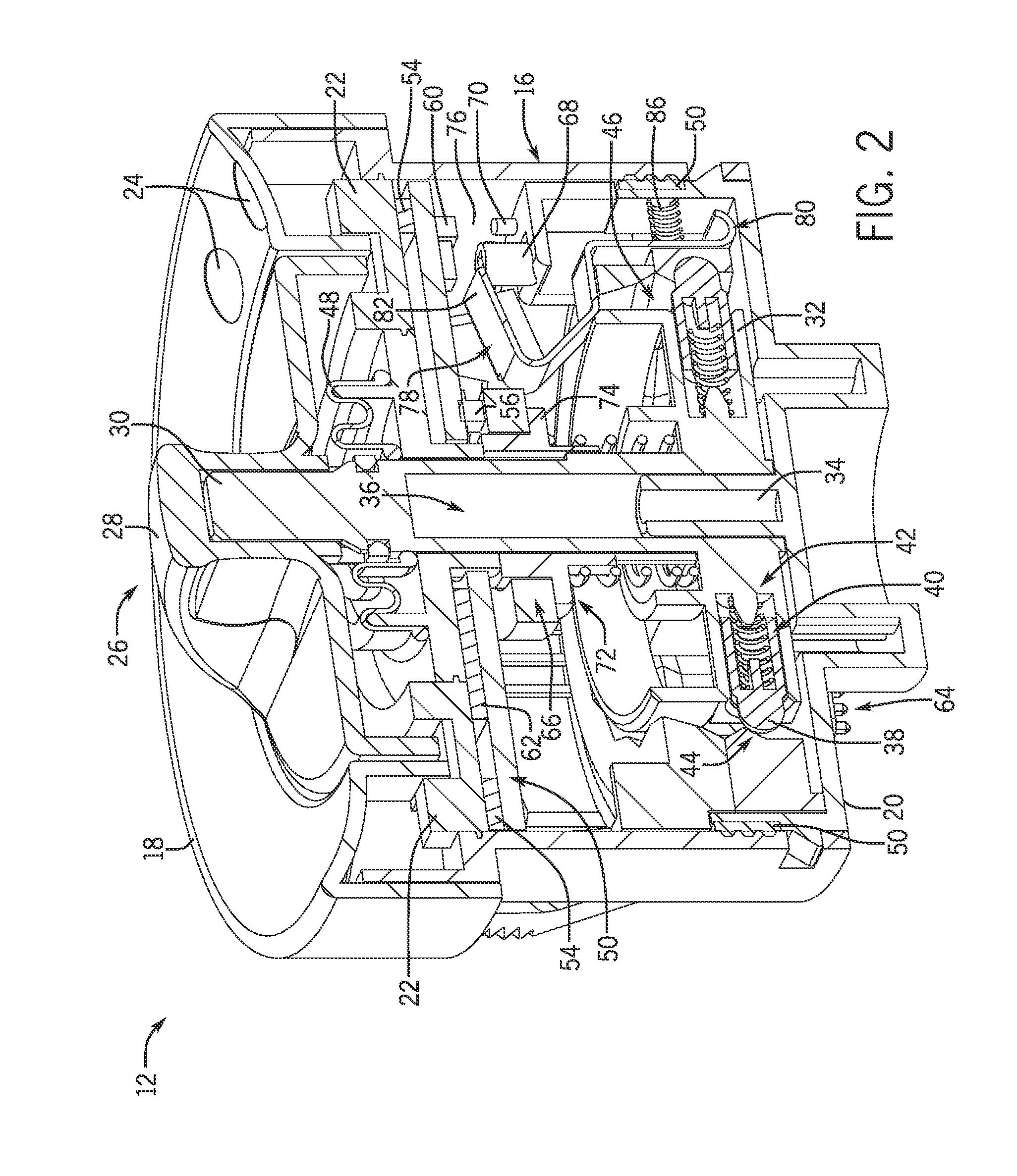
[0021]Embodiments of the invention are directed to a contactless rotary pull switch that utilizes magnetic sensing for both the rotary position and the pull position of the switch, so as to provide robust sensing of the rotary position and pull position. While a contactless rotary pull switch is described below with respect to its use as a vehicle lighting switch, it is recognized that the switch may be instead be used in other applications according to embodiments of the invention. Accordingly, it is to be understood that embodiments of the invention are not limited for use as vehicle lighting switches or for use in vehicles in general and that use of embodiments of the invention for other applications is understood to be within the scope of the invention.

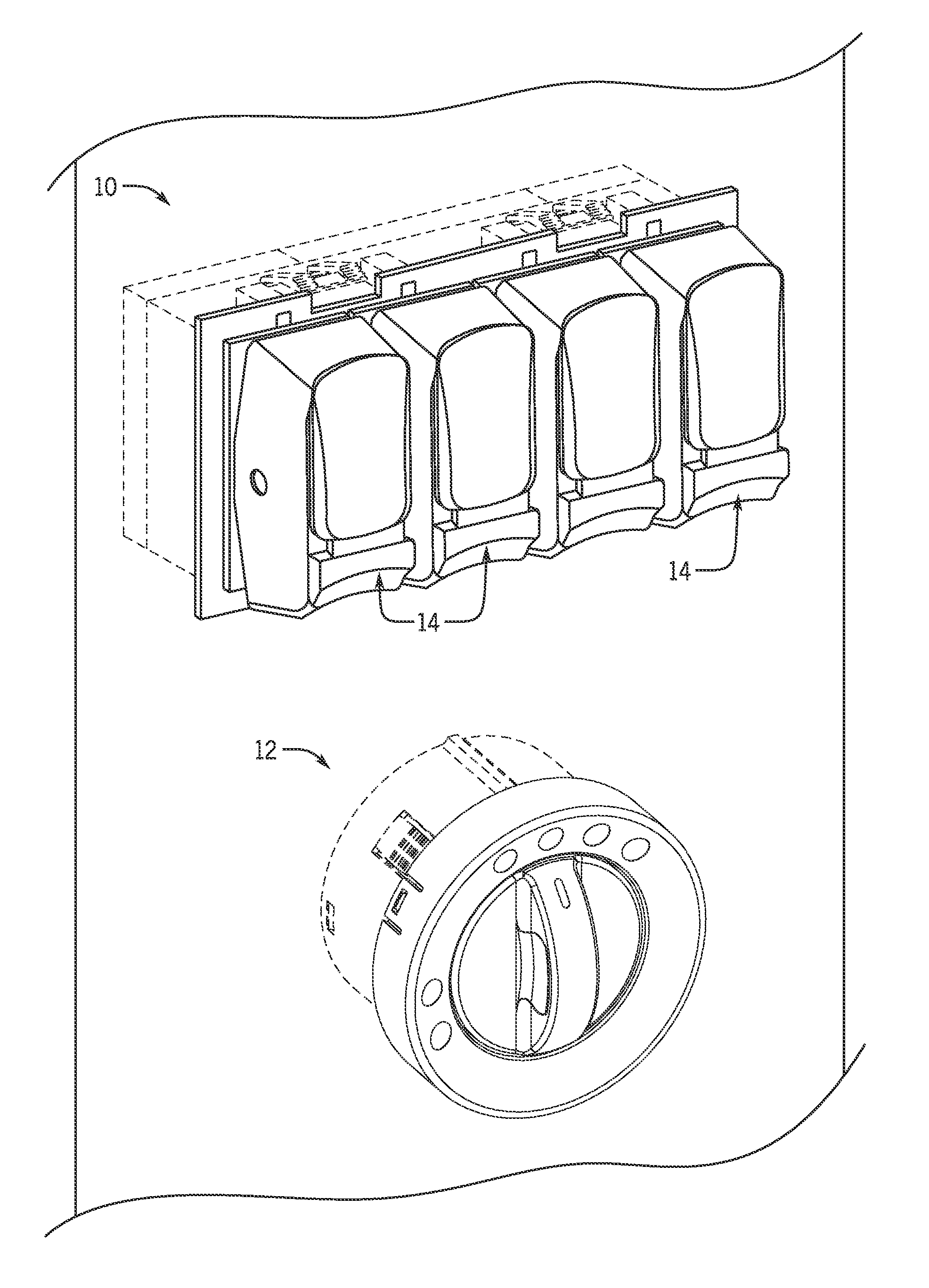
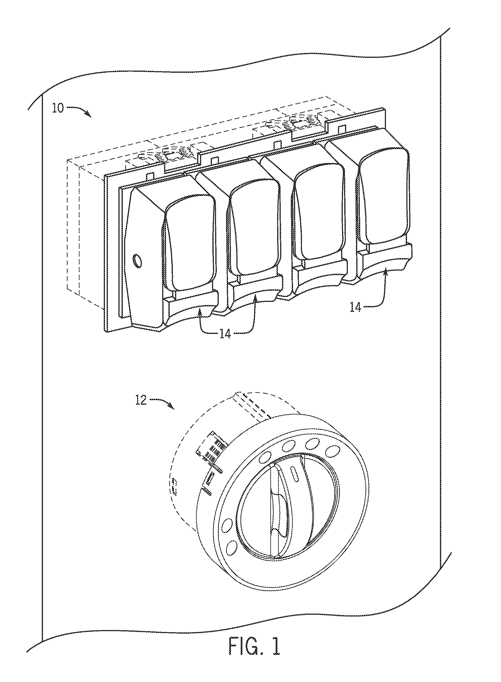
[0022]Referring to FIG. 1, the general layout of a portion of a vehicle dashboard 10 is shown such as might be useable with embodiments of the invention. The dashboard 10 includes a contactless rotary pull switch 12 and other vehi...


PUM


Abstract

A contactless rotary pull switch includes a switch knob assembly rotatable about an axis to a plurality of rotational positions and actuatable to at least one pull position, with the switch knob assembly including a knob element and a rotational shaft fixedly coupled thereto. A rotational magnet is coupled to the rotational shaft so as to rotate therewith, and at least one pull magnet is positioned separately from the rotational magnet. A rotational sensor senses a magnetic field generated by the rotational magnet to identify a rotational position of the switch knob assembly and at least one pull sensor senses a magnetic field generated by the pull magnet(s) to identify a pull position of the switch knob assembly. A rotatable arm member selectively enables/inhibits sensing of the magnetic field generated by the pull magnet(s) by the at pull sensor(s), to identify distinct pull positions of the switch knob assembly.

Description

BACKGROUND OF THE INVENTION[0001]Embodiments of the invention relate generally to rotary pull switches and, more particularly, to contactless rotary pull switches such as might be used as lighting switches for a motor vehicle.[0002]In specialty vehicle markets—such as heavy trucks, agricultural equipment, and construction equipment, for example—various types of electrical switches are used as control switches for a variety of applications, including general vehicle features / applications (e.g., switching the motor vehicle lighting, the windshield wipers, the rear windshield heating, the cruise control functions, etc., on and off) and critical or safety related vehicle features / applications (e.g., power take-off (PTO) switches, “e-stop” type switches, etc.). With respect to a vehicle lighting switch in particular, a typical vehicle lighting switch includes a rotary control having at least three positions: all lights (parking lamps and headlamps) OFF, parking lamps ON, and all lights O...

Claims


Application Information

Patent Timeline
Patent Type & Authority Applications(United States)
IPC IPC(8): H03K17/97B60Q1/14H01H25/06
CPCH03K17/97H01H25/06B60Q1/1461H03K2217/94068H01H36/008H01H2219/036H01H36/004H01H36/00H01H2221/01H03K2017/9713
Inventor LEE, DAVIN ROBERT
Owner EATON INTELLIGENT POWER LIMITED
Why Eureka
Try Eureka