Cylinder control device

Inactive Publication Date: 2015-10-22
KYB CORP
View PDF2 Cites 4 Cited by
  • Summary
  • Abstract
  • Description
  • Claims
  • Application Information

AI Technical Summary

Benefits of technology

[0003]In the cylinder control device shown in FIGS. 10 and 11 of JP2006-105226A, a slow return valve is disposed in an oil passage connecting the cylinder to the operation check valve. The slow return valve is configured to pass working oil flowing into the cylinder freely and to apply resistance to working oil discharged fr

Problems solved by technology

As described above, the cylinder control device disclosed in JP2006-105226A includes the slow return valve in addition to the operation check

Method used


Image

  • Cylinder control device
  • Cylinder control device
  • Cylinder control device

Examples


Example

First Embodiment

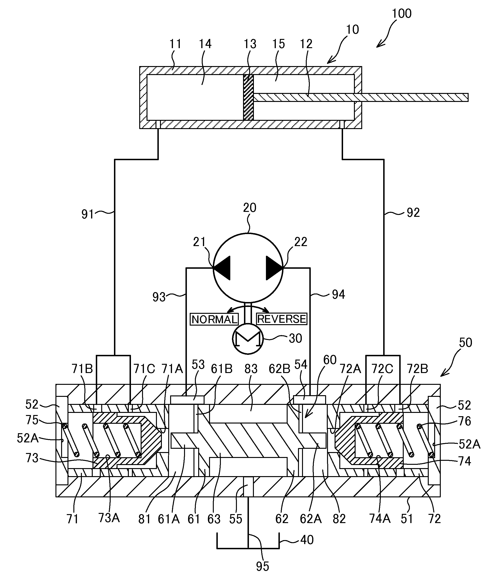
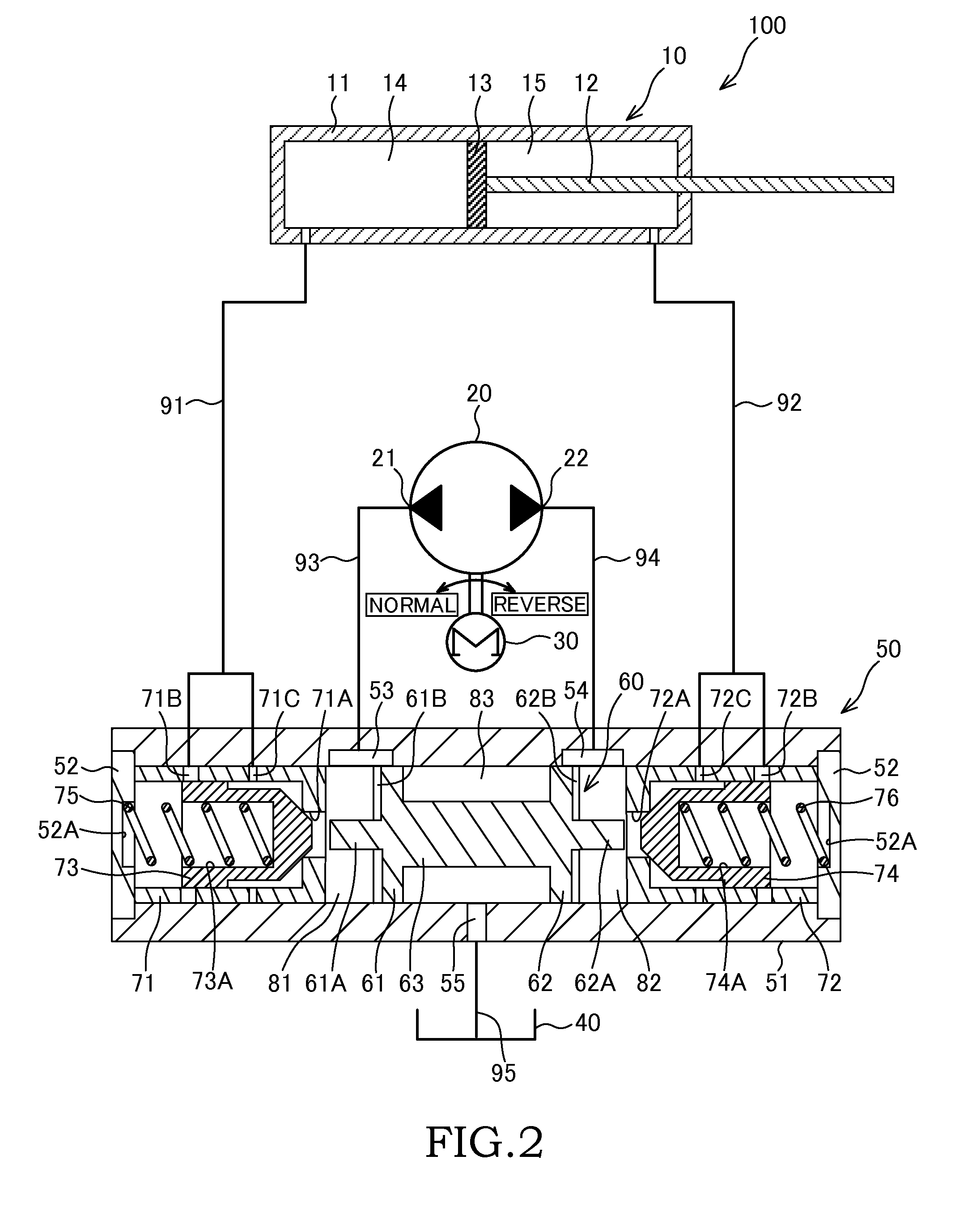
[0025]Referring to FIGS. 1 to 4, a cylinder control device 100 according to a first embodiment of this invention will be described.

[0026]Referring to FIGS. 1 and 2, a configuration of the cylinder control device 100 will be described.

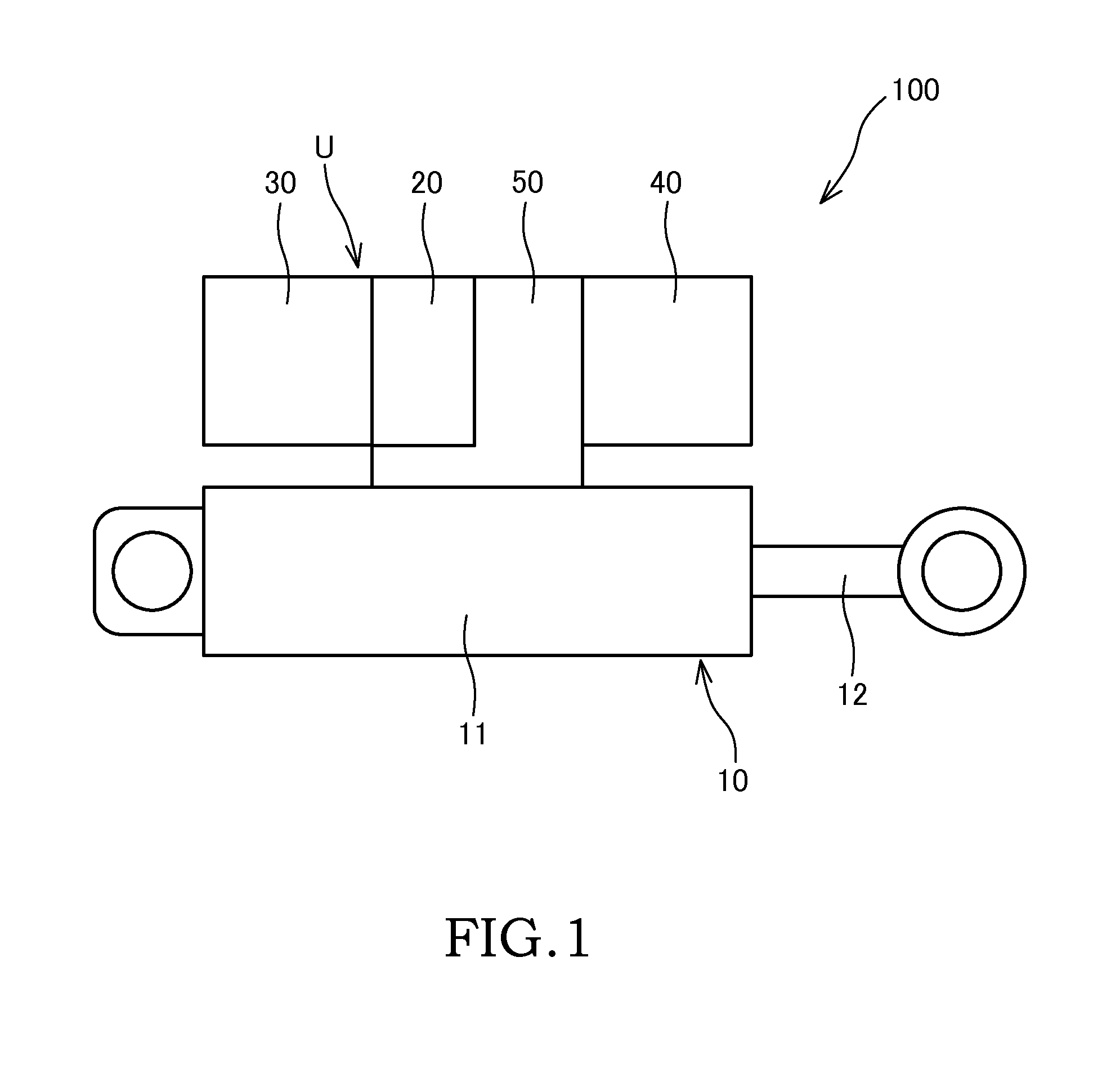
[0027]The cylinder control device 100 shown in FIGS. 1 and 2 is installed in an agricultural instrument, a working instrument, or the like in order to control expansion and contraction operations of a cylinder 10 using working oil.

[0028]The cylinder control device 100 includes the cylinder 10, which is configured to be capable of expanding and contracting, a pump 20 that pumps the working oil as a working fluid, a drive motor 30 that drives the pump 20, a tank 40 that stores the working oil, and a control valve 50 that controls respective flows of the working oil between the cylinder 10 and the pump 20 and between the pump 20 and the tank 40.

[0029]The pump 20, the drive motor 30, the tank 40, the control valve 50, and so on together cons...

Example

Second Embodiment

[0088]Next, referring to FIGS. 5 to 8, a cylinder control device 200 according to a second embodiment of this invention will be described. The following description focuses on differences with the first embodiment. Identical configurations to the cylinder control device 100 according to the first embodiment have been allocated identical reference symbols, and description thereof has been omitted.

[0089]In the cylinder control device 100 according to the first embodiment, described above, the communicating passages 71B, 72B and the throttle passages 71C, 72C formed respectively in the first and second sleeves 71, 72 serve as the supply / discharge ports that connect the first and second valve chambers 81, 82 to the first and second cylinder passages 91, 92. The diameters of the throttle passages 71C, 72C are determined in advance in accordance with the envisaged external force acting on the cylinder.

[0090]In other words, in the first embodiment, when a greater external ...

Example

Third Embodiment

[0131]Next, referring to FIGS. 10 to 12, a cylinder control device 300 according to a third embodiment of this invention will be described. The following description focuses on differences with the second embodiment. Identical configurations to the cylinder control device 200 according to the second embodiment have been allocated identical reference symbols, and description thereof has been omitted.

[0132]In the cylinder control device 200 according to the second embodiment, described above, the pluralities of through holes 71D, 72D formed respectively in the first and second sleeves 71, 72 serve as the supply / discharge ports connecting the first and second valve chambers 81, 82 to the first and second cylinder passages 91, 92. The pluralities of through holes 71D, 72D are configured such that as the first and second valve bodies 73, 74 slide due to be biased by the first and second springs 75, 76, the number of open through holes 71D, 72D is reduced, leading to an in...


PUM


Abstract

In a cylinder control device comprising a control valve that controls a flow of working fluid flowing between a cylinder and a pump, the control valve includes a spool provided in a main body portion, a sleeve that is provided in the main body portion opposite each of two end portions of the spool, and includes a communicating port that communicates with a valve chamber, a communicating passage that communicates with a cylinder chamber, and a throttle passage that communicates with the cylinder chamber, a valve body provided in the sleeve to control a communication state between the communicating port and the communicating passage and throttle passage in accordance with a sliding position thereof, and a biasing member that biases the valve body in a valve closing direction.

Description

TECHNICAL FIELD[0001]This invention relates to a cylinder control device that controls expansion and contraction operations of a cylinder using a working fluid.BACKGROUND ART[0002]JP2006-105226A discloses a hydraulic cylinder control device including a cylinder, a pump that pumps working oil as a working fluid, a tank that stores the working oil, a switch valve that controls a flow of the working oil between the pump and the tank, and an operation check valve that controls a flow of the working oil between the cylinder and the pump.SUMMARY OF INVENTION[0003]In the cylinder control device shown in FIGS. 10 and 11 of JP2006-105226A, a slow return valve is disposed in an oil passage connecting the cylinder to the operation check valve. The slow return valve is configured to pass working oil flowing into the cylinder freely and to apply resistance to working oil discharged from the cylinder. The slow return valve is thus capable of preventing hunting that occurs when the operation check...

Claims


Application Information

Patent Timeline
IPC IPC(8): F15B11/04F15B15/18F15B11/08
CPCF15B11/04F15B15/18F15B11/08F15B13/01F15B2211/785F15B2211/27F15B7/006F15B2211/20561
Inventor KUBOTA, TAKUYAMASUTA, YUUZOU
Owner KYB CORP
Why Eureka
Try Eureka