Engine valve control device

a control device and engine valve technology, applied in electrical control, non-mechanical valves, couplings, etc., can solve the problems of excessive correction, inability to cancel steady-state deviation, slow response speed of actual phase with respect to change of target phase, etc., to improve controllability and controllability, e.g., quick reaction properties

Active Publication Date: 2012-08-14
DENSO CORP
View PDF4 Cites 3 Cited by
  • Summary
  • Abstract
  • Description
  • Claims
  • Application Information

AI Technical Summary

Benefits of technology

[0010]It is an object of the present invention to provide an engine valve control device that inhibits hunting of an actual rotation phase with respect to a target phase.

Problems solved by technology

That is, response speed of the actual phase with respect to change of the target phase becomes slow.
Moreover, the steady-state deviation cannot be canceled by correcting the holding value only once when the temperature is low.
Therefore, the holding value is corrected multiple times, thereby causing excessive correction.
If the control command value is calculated based on the holding value corrected excessively in this way and the control valve is controlled, there occurs a concern that the actual phase hunts largely with respect to the target phase.

Method used


Image

  • Engine valve control device
  • Engine valve control device
  • Engine valve control device

Examples


first embodiment

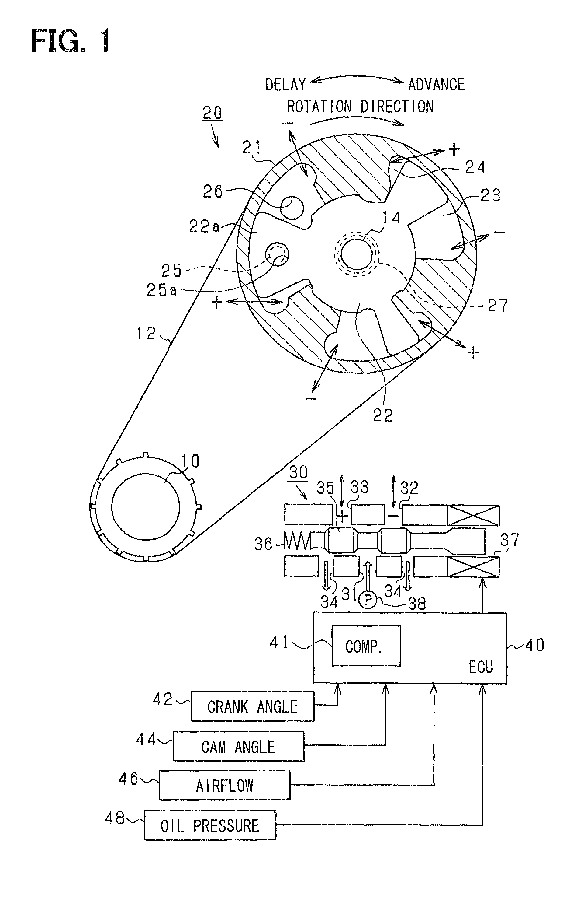
[0039]FIG. 1 shows an entire construction of an engine valve control mechanism according to a first embodiment of the present invention.

[0040]In FIG. 1, a power of a crankshaft 10 (output shaft) of an engine (internal combustion engine) is transmitted to a camshaft 14 via a belt 12 and a valve timing adjusting device 20 (referred to as VVT, hereafter). The VVT 20 has a first rotating body 21 (housing) mechanically linked with the crankshaft 10 and a second rotating body 22 (vane rotor) mechanically linked with the camshaft 14. In the present embodiment, the second rotating body 22 has multiple protrusions 22a (vanes) and is accommodated in the first rotating body 21. The protrusions 22a of the second rotating body 22 and an inner wall of the first rotating body 21 define delay chambers 23 and advance chambers 24. The delay chambers 23 delay a rotation angle (i.e., relative rotation phase) of the camshaft 14 relative to the crankshaft 10. The advance chambers 24 advance the relative ...

second embodiment

[0072]Next, a second embodiment of the present invention will be described.

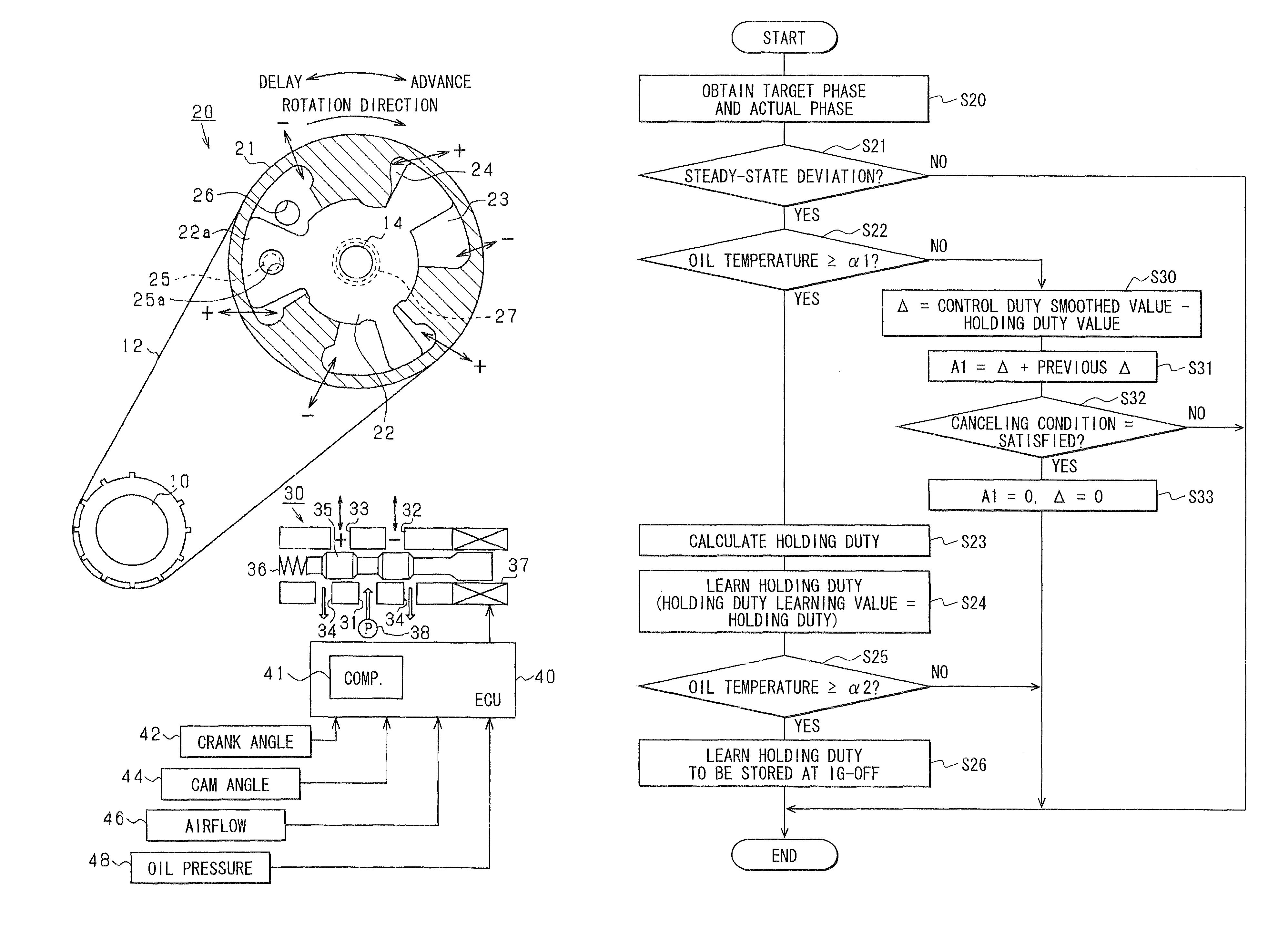
[0073]In the above-described first embodiment, the control duty is calculated based on the holding duty learning value and the feedback correction values (proportional term duty and differential term duty). In the second embodiment, the control duty is calculated by taking into account a steady-state deviation correction value A1 explained below in addition to the holding duty learning value and the feedback correction values. Hereafter, processing contents according to the present embodiment shown in FIGS. 6 and 7 will be explained, focusing on differences from FIGS. 2 and 4.

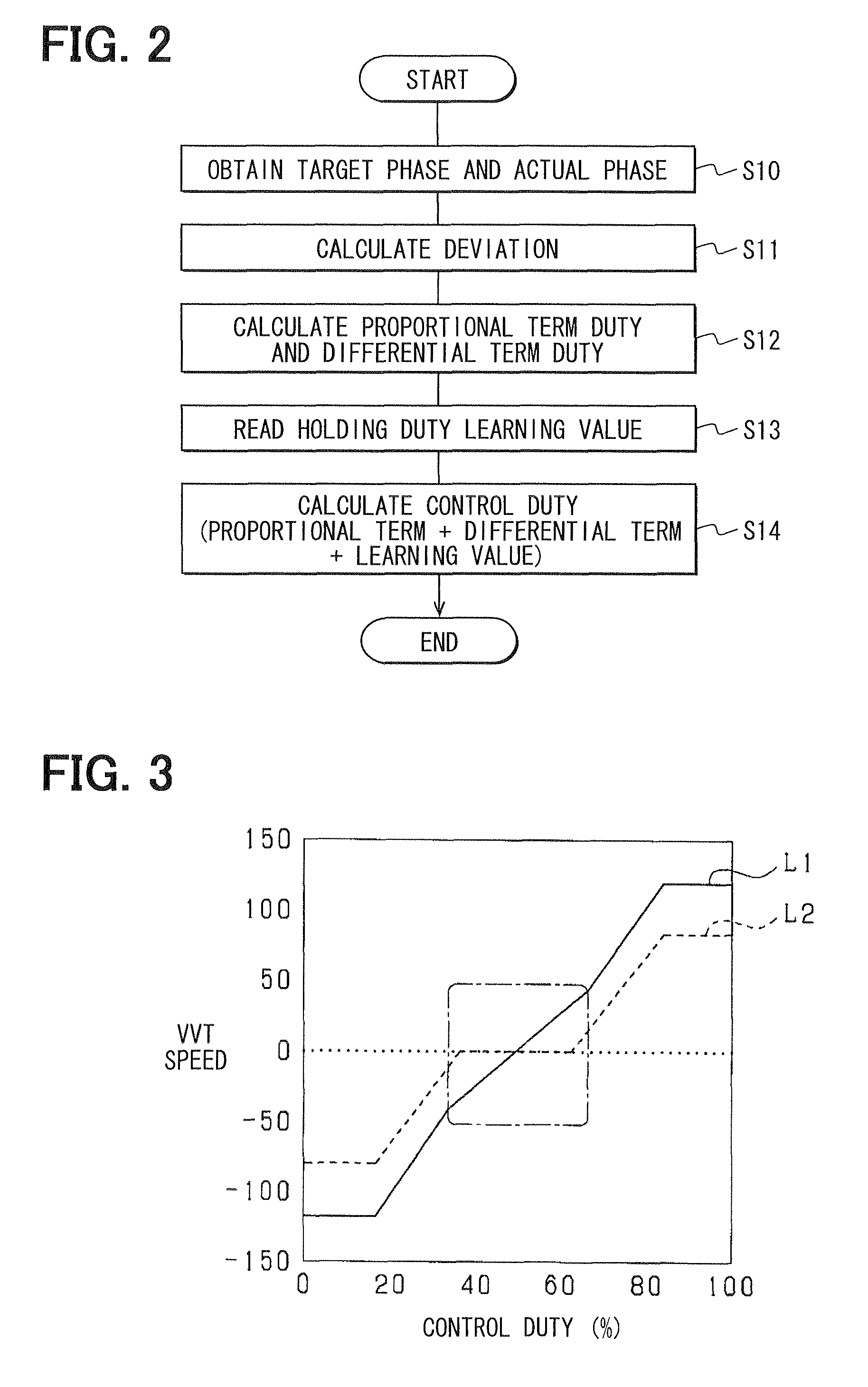
[0074]First in S10 to S13 of FIG. 6, like the processing shown in FIG. 2, the actual phase and the target phase are obtained (S10), the deviation between the obtained phases is calculated (S11), and the feedback correction values are calculated based on the calculated deviation (S12). In following S13, the learning value of the holding d...

third embodiment

[0094]Next, a third embodiment of the present invention will be explained.

[0095]In the above-described second embodiment, the control duty is calculated based on the holding duty learning value, the feedback correction values (proportional term duty and differential term duty) and the steady-state deviation correction value A1. In the third embodiment, the control duty is calculated by taking into account an oil pressure correction value A2 and a phase correction value A3 explained below in addition to the holding duty learning value, the feedback correction values and the steady-state deviation correction value A1. Hereafter, processing contents according to the present embodiment shown in FIGS. 9 and 10 will be explained, focusing on differences from FIG. 6. In the present embodiment, processing similar to the processing of FIG. 7 of the second embodiment is performed in addition to the processing of FIGS. 9 and 10.

[0096]First in S10 to S13 and S131 of FIG. 9, like the processing ...


PUM


Abstract

An engine valve control device is applied to an engine valve control mechanism having a VVT (valve timing adjusting device), an OCV (control valve) that controls a flow of hydraulic oil supplied to the VVT, and an electromagnetic solenoid that controls an operation of the OCV according to a control duty (control command value). The engine valve control device calculates the control duty based on a holding duty, which occurs when an actual phase does not change but is held, and feedback correction values. The engine valve control device corrects the value of the holding duty in accordance with a steady-state deviation between the actual phase and a target phase to perform learning for storing and updating the holding duty value. If temperature of the hydraulic oil is low, the learning is prohibited even when the steady-state deviation is occurring.

Description

CROSS REFERENCE TO RELATED APPLICATION[0001]This application is based on and incorporates herein by reference Japanese Patent Application No. 2009-169634 filed on Jul. 20, 2009.BACKGROUND OF THE INVENTION[0002]1. Field of the Invention[0003]The present invention relates to an engine valve control device applied to an engine valve control mechanism that adjusts opening-closing timings of an exhaust valve or an intake valve (engine valve) of an internal combustion engine.[0004]2. Description of Related Art[0005]Generally, an engine valve control mechanism that adjusts opening-closing timings of an engine valve includes a hydraulic actuator that varies a rotation phase of a camshaft with respect to a crankshaft, a control valve that controls a flow of hydraulic oil supplied to the hydraulic actuator, and an electromagnetic solenoid that controls an operation of the control valve according to a control command value.[0006]For example, according to a calculation method of the control com...

Claims


Application Information

Patent Timeline
Patent Type & Authority Patents(United States)
IPC IPC(8): F01L1/34
CPCF01L1/34F01L1/3442F02D41/0002F02D41/20F02D41/2448F02D41/2464F02D2041/001F02D2041/2027F02D2200/023Y02T10/42Y02T10/40
Inventor WADA, MINORU
Owner DENSO CORP
Why Eureka
Try Eureka