Actuator control device

a control device and actuator technology, applied in the field of actua, can solve the problems of not being able to say, including errors in measured values, etc., and achieve the effects of reducing component cost and printed substrate size, preventing hunting, and reducing the size and cost of the lower-level control uni

Inactive Publication Date: 2014-12-04
DAIKIN IND LTD
View PDF1 Cites 2 Cited by
  • Summary
  • Abstract
  • Description
  • Claims
  • Application Information

AI Technical Summary

Benefits of technology

[0021]In the actuator control device according to the first or second aspects of the present invention, the difference between the actual value and the target value of the predetermined control factor for the actuator requested by the upper-level control unit is reduced.
[0022]In the actuator control device according to the third aspect of the present invention, since it is only necessary to monitor the same control factor, it is possible to reduce component cost and printed substrate size by, e.g., shared use of the detection circuit or other elements.
[0023]In the actuator control device according to the fourth aspect of the present invention, the configuration is such that tracking of the upper-level target value is performed after the result of the previous control takes effect, therefore making it possible to prevent hunting.
[0024]In the actuator control device according to the fifth aspect, the command input element, the actuator control element, and the tracking element are modularized in a single package, thereby making it possible to reduce the size and the cost of the lower-level control unit.
[0025]In the actuator control device according to the sixth aspect, in an example in which, e.g., the upper-level control unit, the lower-level control unit, and the intermediate control unit are mounted on a single printed substrate, the area occupied by the all of the mounted items on the printed substrate decreases, making it possible to reduce the size of the printed substrate.
[0026]In the actuator control device according to the seventh aspect, in order to match the actual rotation speed of the motor with the upper-level target value, prior to the upper-level target value being inputted into the command input element, the intermediate control unit increases or decreases the upper-level target value, therefore reducing the difference between the actual rotation speed and the rotation speed of the motor requested by the upper-level control unit.

Problems solved by technology

However, the former presents an inconvenience in that, as pointed out in Patent Literature 1, the current detector and the current adjuster must be selected according to the current capacity of the motor.
Therefore, an error with respect to the measured value is included, and it cannot be said that the motor output tracks the command input from an upper-level control unit in an accurate manner.

Method used


Image

  • Actuator control device
  • Actuator control device
  • Actuator control device

Examples


modification examples

(4) MODIFICATION EXAMPLES

(4-1) First Modification Example

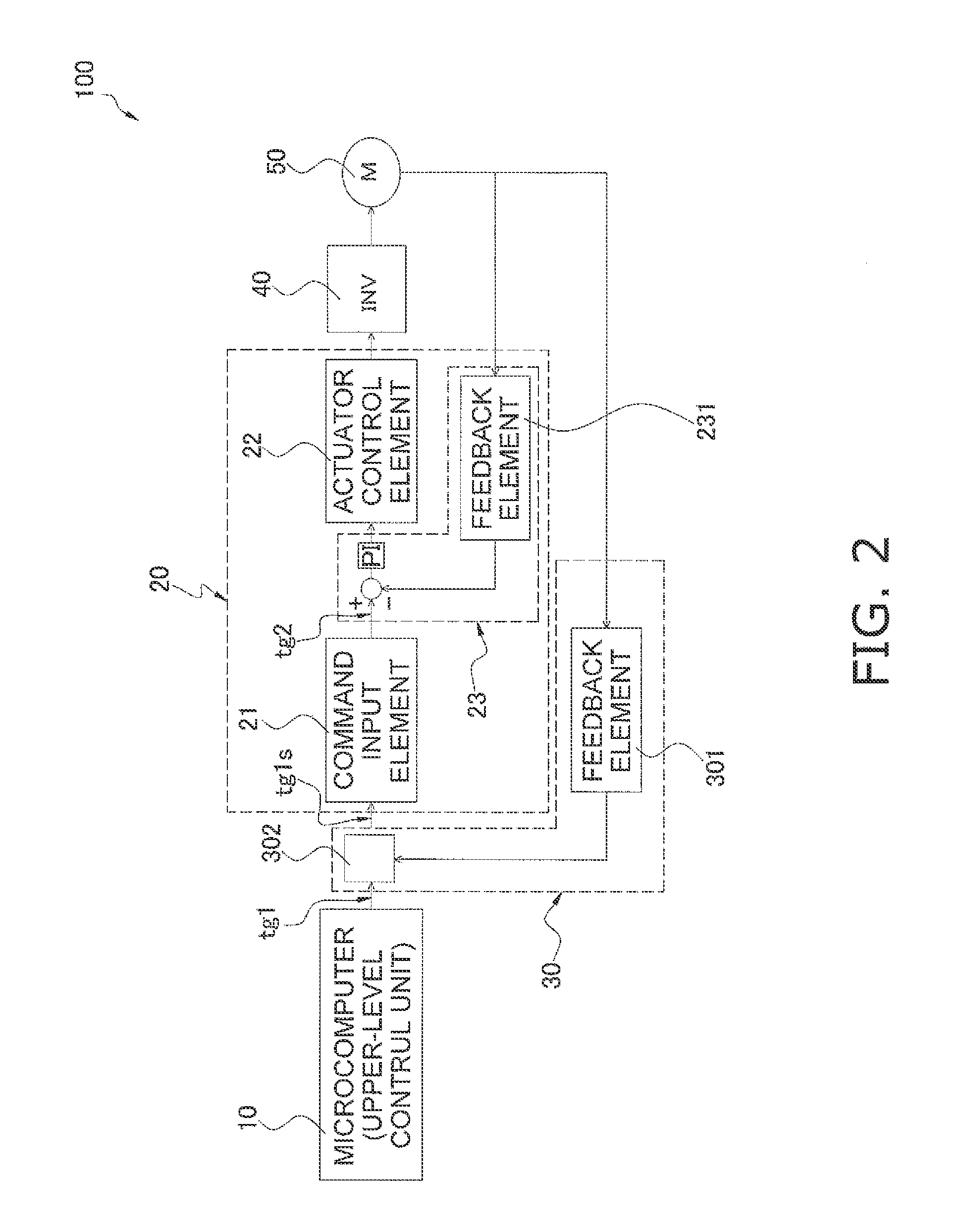
[0065]In the above embodiment, each of the tracking element 23 and the intermediate control unit 30 includes a feedback element as disclosed in FIG. 2; however, this is not provided by way of limitation. A description will now be given with reference to FIG. 4.

[0066]FIG. 4 is a control block diagram of the motor control device 100 according to a first modification example. In FIG. 4, the tracking element 23 and the intermediate control unit 30 share the rotation speed computation unit 231, which is a feedback element. It is thereby possible to reduce the size and the cost of the motor control device 100.

[0067]The control factor in the intermediate control unit 30 is, as with the tracking element 23, the rotation speed of the brushless DC motor 50. However, the adjustment unit 302 may perform an adjustment to a value that can be subjected to a subtraction process with respect to the upper-level target value tg1. In such an inst...


PUM


Abstract

An actuator control device includes an upper-level control unit that sets an upper-level target value of a predetermined control factor relating to driving an actuator, a lower level control unit, and an intermediate control unit. The lower-level control unit has a command input element that receives an input of the upper-level target value and outputs a lower-level target value of the predetermined control factor, an actuator control element that receives an input of the lower-level target value and controls the actuator, and a tracking element that causes an actual value of the predetermined control factor in the actuator to track the lower-level target value. The intermediate control unit causes the actual value of the predetermined control factor in the actuator to track the upper-level target value. The upper-level target value is inputted into the command input element of the lower-level control unit via the intermediate control unit.

Description

TECHNICAL HELD[0001]The present invention relates to an actuator control device, and particularly to an actuator control device suitable for controlling of a motor.BACKGROUND ART[0002]When an actuator such as a motor is controlled using an IC in which there is a large amount of variation in the command input circuit into which a command from, e.g., a microcomputer is inputted, instances occur in which the output of the actuator does not follow the command as required by the microcomputer.[0003]There is known, as a technique for solving this problem, e.g., in relation to a motor, a speed control device disclosed in the prior art in Patent Literature 1 (JP-A 58-99279). In this speed control device, a current minor control loop comprising a current detector and a current adjuster is provided to a speed adjustment loop comprising a speed detector and a speed adjuster, and the actual speed of the motor is controlled so as to reach the target speed.[0004]This Patent Literature also propos...

Claims


Application Information

Patent Timeline
Patent Type & Authority Applications(United States)
IPC IPC(8): H02P6/08H02P29/00
CPCH02P6/08H02P6/06H02P23/22H02P29/00
Inventor SATO, TOSHIAKIYAGI, SATOSHI
Owner DAIKIN IND LTD
Why Eureka
Try Eureka