Vibration damping device for railway vehicle

a technology for railway vehicles and damping devices, which is applied in the direction of shock absorbers, servomotors, transportation and packaging, etc., can solve the problems of excessive thrust and extremely high pressure in the cylinder, and achieve the effects of preventing the hunting of thrust, reducing the pressure of the cylinder, and improving the damping

Active Publication Date: 2016-05-03
KYB CORP
View PDF19 Cites 2 Cited by
  • Summary
  • Abstract
  • Description
  • Claims
  • Application Information

AI Technical Summary

Benefits of technology

[0006]In a case of feedback control of the thrust of the actuator, an excessive thrust increases a deviation between a control command and the thrust, and hence hunting occurs which the thrust of the actuator continuously varies. As a result, vibration of the body may be aggravated.
[0007]It is an object of the present invention to provide a vibration damping device for railway vehicle capable of preventing hunting of the thrust when a temperature of the hydraulic fluid is low, capable of exerting a stable thrust, and capable of effectively suppressing vibration of the body.

Problems solved by technology

Accordingly, in a case where the actuator is caused to exert a relatively small thrust, a pressure loss due to resistance in the variable relief valve, a pipe, and the like is increased, and hence a pressure in the cylinder is extremely high, with the result that the thrust is excessive.
In a case of feedback control of the thrust of the actuator, an excessive thrust increases a deviation between a control command and the thrust, and hence hunting occurs which the thrust of the actuator continuously varies.

Method used


Image

  • Vibration damping device for railway vehicle
  • Vibration damping device for railway vehicle
  • Vibration damping device for railway vehicle

Examples


Embodiment Construction

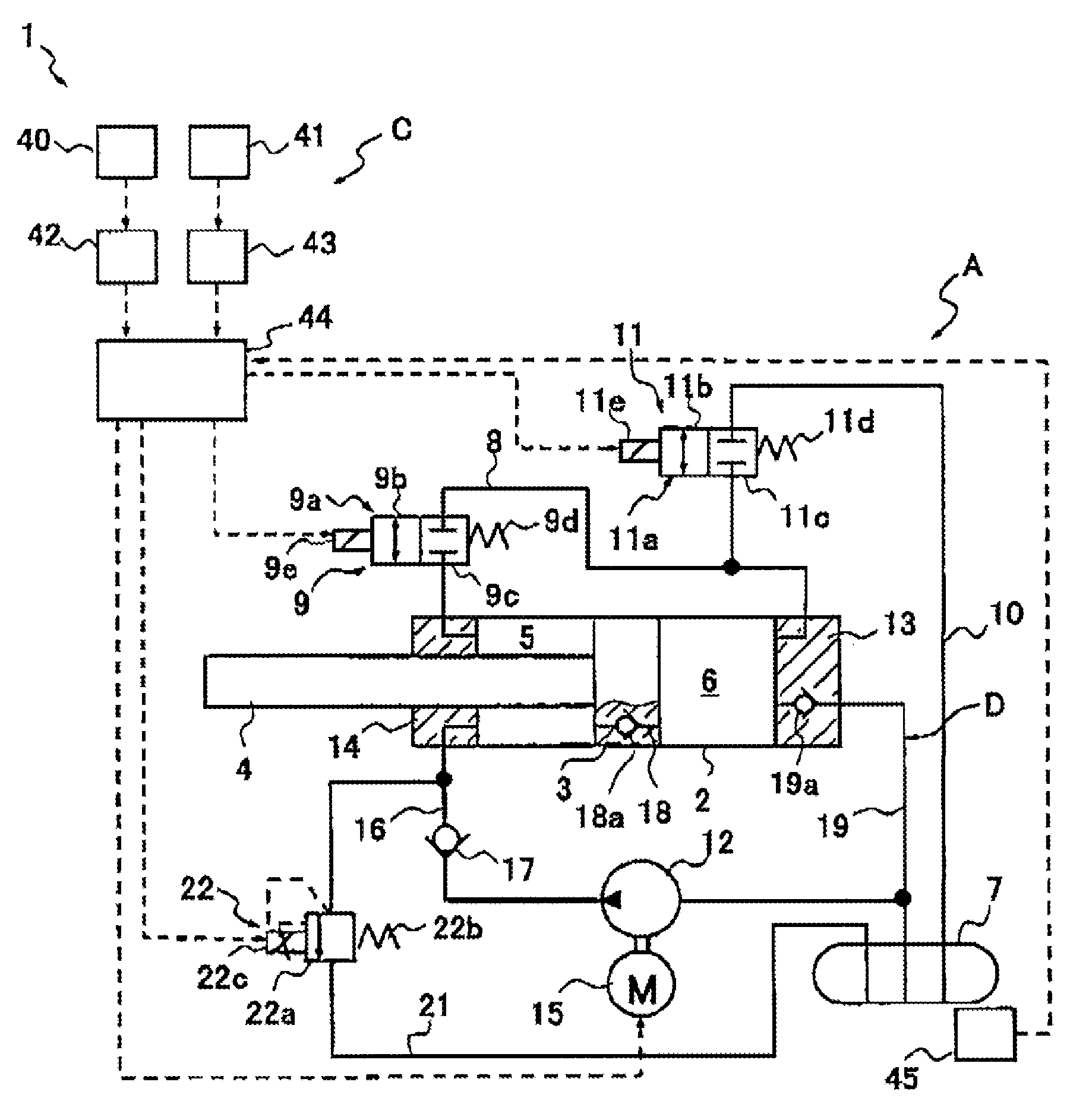
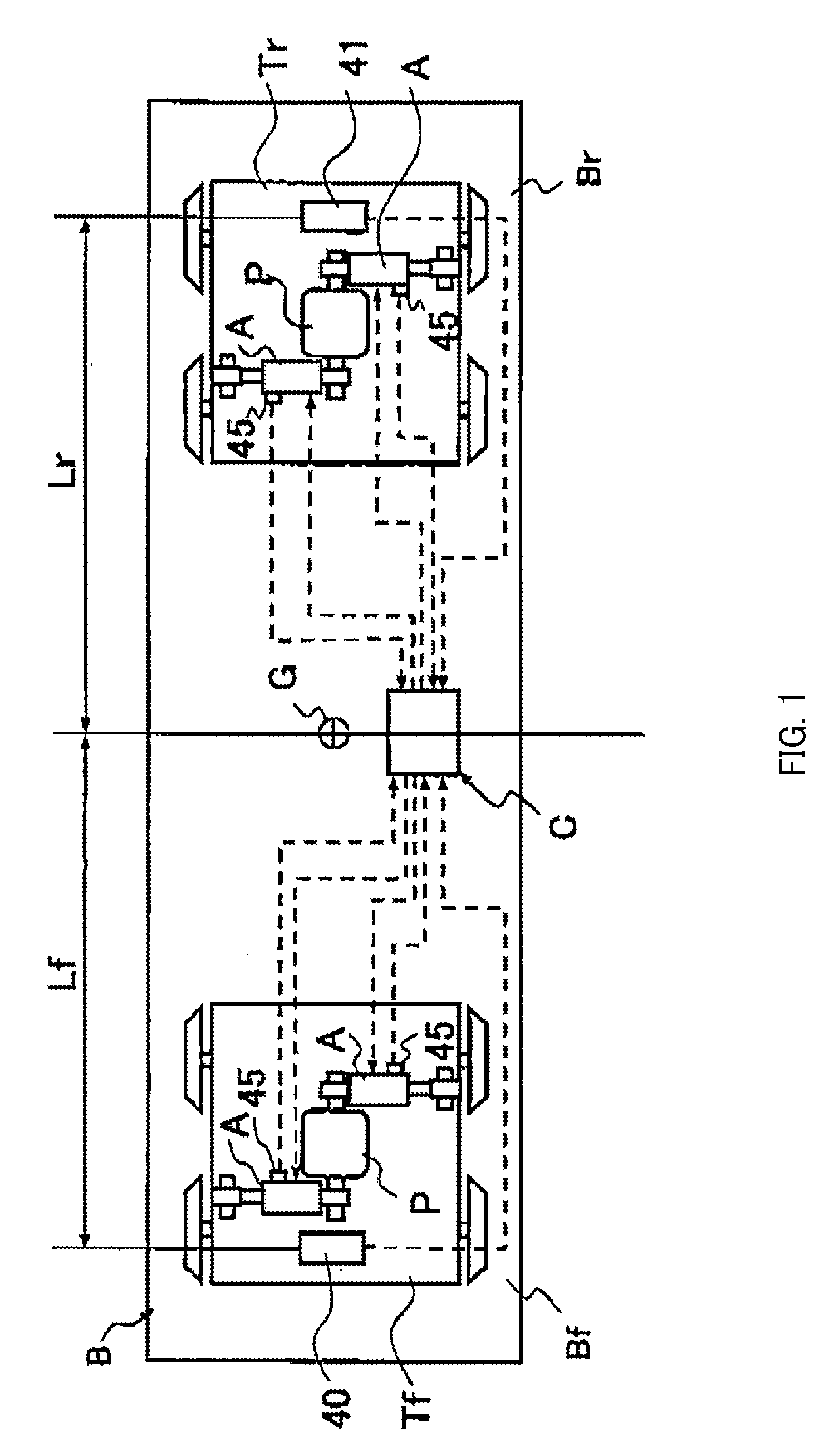
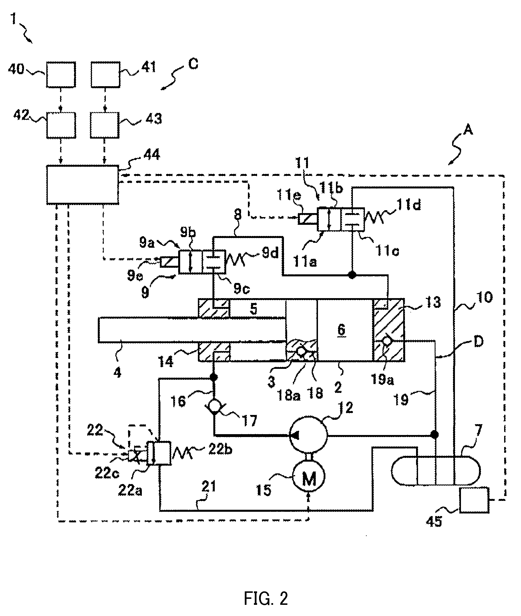
[0015]A vibration damping device for railway vehicle 1 according to an embodiment of the present invention is used as a vibration damping device for a body B of a railway vehicle. As illustrated in FIG. 1, the vibration damping device for railway vehicle 1 includes pairs of actuators A interposed between a front truck Tf and the body B and between a rear truck Tr and the body B, a damper circuit D (FIG. 2) for causing the actuators A to function as dampers, and a controller C for controlling the actuators A so as to suppress vibration of the body B.

[0016]Each pair of actuators A is coupled to a pin P suspended below the body B of the railway vehicle, and is interposed in parallel between the body B and the front truck Tf and between the body B and the rear truck Tr.

[0017]The four actuators A perform active control to suppress horizontal vibration of the body B with respect to a vehicle advancing direction. The controller C controls all of the actuators A to suppress lateral vibratio...


PUM


Abstract

A vibration damping device for railway vehicle includes an actuator and a damper circuit that causes the actuator to function as a damper. The actuator includes a cylinder coupled to a truck of a railway vehicle, a piston, a rod coupled to the piston and a body, a rod-side chamber and a piston-side chamber inside the cylinder, a first on-off valve for a first passage that communicates between a rod-side chamber and a piston-side chamber, a second on-off valve for a second passage that communicates between the piston-side chamber and a tank, and a pump that supplies a hydraulic fluid into the rod-side chamber. The hydraulic fluid has such kinematic viscosity-temperature characteristics that a kinematic viscosity of the hydraulic fluid ranges from 7 mm2 / s to 50 mm2 / s in a temperature range of from 20° C. to 60° C.

Description

TECHNICAL FIELD[0001]The present invention relates to an improvement of a vibration damping device for railway vehicle.BACKGROUND ART[0002]A vibration damping device for railway vehicle is known to be interposed between a body and a truck of a railway vehicle, and to suppress vibration that acts on the railway vehicle and occurs in a right-and-left direction with respect to an advancing direction of the body.[0003]JP 2010-65797 A discloses a vibration damping device for railway vehicle. The vibration damping device for railway vehicle includes a cylinder coupled to one of a truck and a body of a railway vehicle, a piston slidably inserted into the cylinder; a rod inserted into the cylinder and coupled to the piston and another one of the truck and the body, a rod-side chamber and a piston-side chamber partitioned by the piston inside the cylinder, a tank, a first on-off valve provided in a middle of a first passage for communicating between the rod-side chamber and the piston-side c...

Claims


Application Information

Patent Timeline
Patent Type & Authority Patents(United States)
IPC IPC(8): F16F9/34F16F9/18B61F5/24F16F9/46F15B7/00F16F9/00F16F9/19
CPCF16F9/18B61F5/245F15B7/006F16F9/006F16F9/19F16F9/46F15B2211/7053F15B2211/785B61F5/24F15B11/028
Inventor OGAWA, TAKAYUKIAOKI, JUNSUZUKI, TSUTOMUUCHIDA, MASARUYABUKI, CHIE
Owner KYB CORP
Why Eureka
Try Eureka