

Image pickup lens
a pickup lens and image technology, applied in the field of image pickup lenses, can solve the problems of insufficient correction of chromatic aberration of magnification, increased distortion in the range of approximately 70% position and above an image height to a maximum image height, and required high aberration correction technique, so as to achieve satisfactory correction of field curvature and distortion, widen angle, and reduce lens size
- Summary
- Abstract
- Description
- Claims
- Application Information
AI Technical Summary
Benefits of technology
Problems solved by technology
Method used
Image

Examples
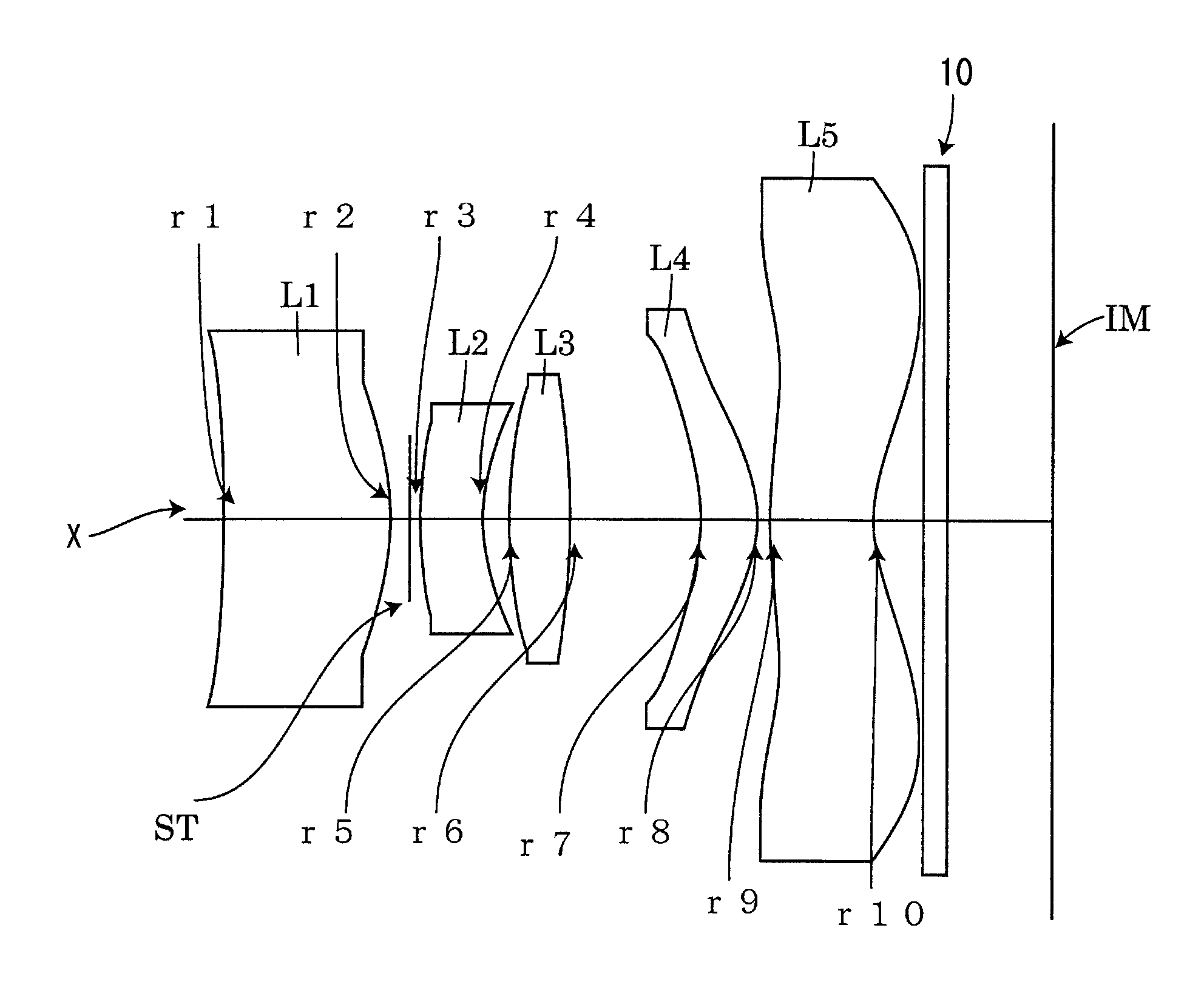
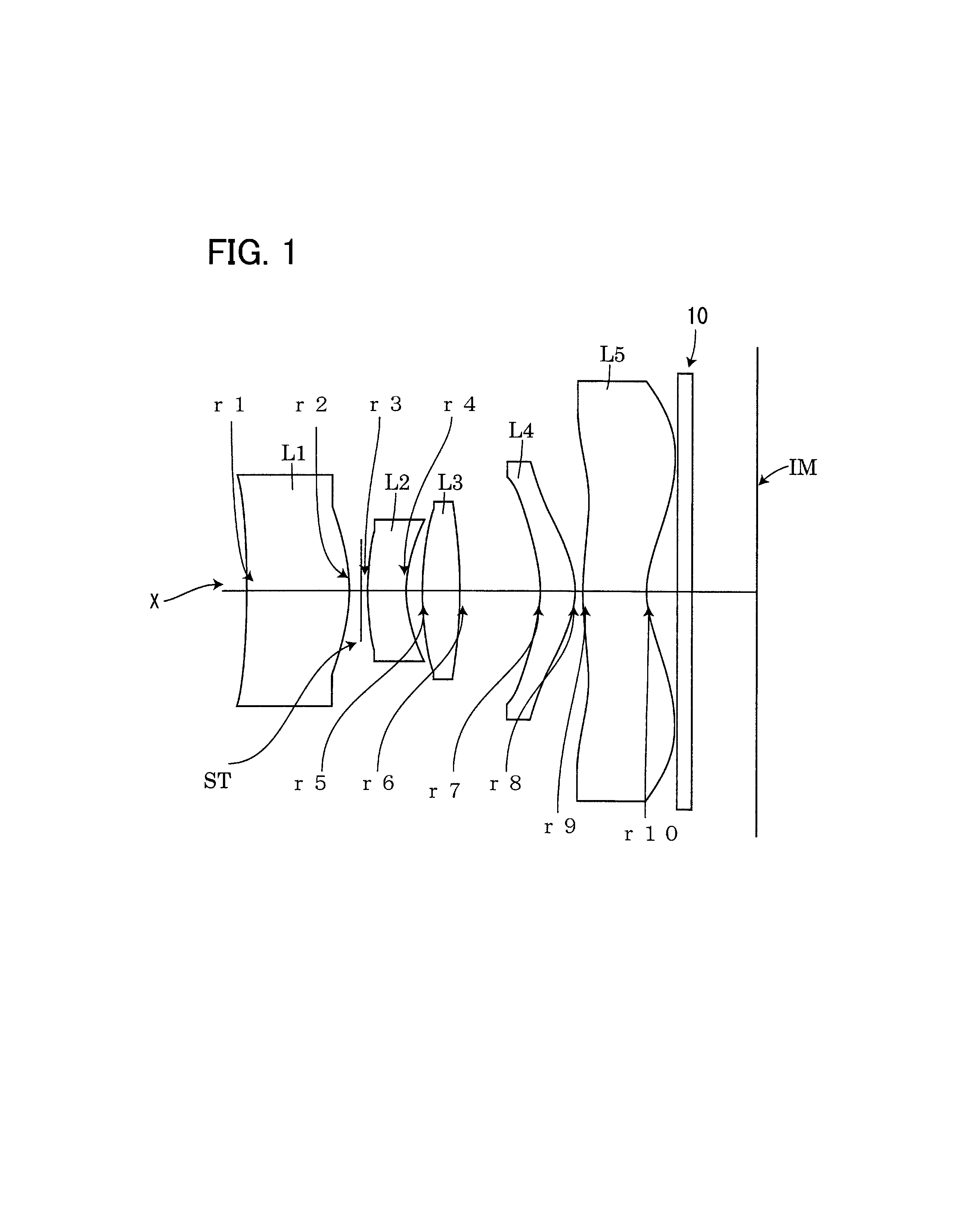
embodiment 1
[0055]Basic lens data will be shown in Table 1 below.
TABLE 1f = 6.3161 mmFno = 3.00ω = 38.09°Surface dataSurface No. iCurvature radius rSurface distance dRefractive index NdAbbe number ν d(Object surface)Infinity450.0 1*−25.002.08601.534656.16 2*−3.22140.2385StopInfinity0.1336 3*5.65700.78271.63423.9 4*2.31940.3283 5*6.22260.76531.534656.16 6*−12.24181.65 7*−2.76460.71271.534656.16 8*−1.69980.15 9*5.70131.30671.534656.1610*1.88890.6211 ∞0.301.516764.1912 ∞1.3005(Image plane)∞Focal length of each lensf1 = 6.665f2 = −6.745f3 = 7.797f4 = 6.663f5 = −5.977Aspheric dataFirstk = 0.00, A4 = −3.3091e−003, A6 = 2.0666e−004,surfaceA8 = −4.343e−005, A10 = 4.063e−006, A12 = 0, A14 = 0, A16 = 0Secondk = −5.7276, A4 = 9.6631e−003, A6 = −7.9901e−003,surfaceA8 = 3.3424e−003, A10 = −7.9921e−004, A12 = 8.3452e−005,A14 = 0, A16 = 0Thirdk = −8.418, A4 = 1.14e−002, A6 = 5.5508e−003,surfaceA8 = 1.3206e−003, A10 = −1.3529e−004, A12 = 0, A14 = 0, A16 = 0Fourthk = −1.5523, A4 = −2.73e−002, A6 = 1.285e−002,su...
embodiment 2
[0061]Basic lens data will be shown in Table 2 below.
TABLE 2f = 5.3411 mmFno = 2.97ω = 42.83°Surface dataSurface No. iCurvature radius rSurface distance dRefractive index NdAbbe number ν d(Object surface)Infinity450.0 1*−17.57723.00611.534656.16 2*−2.83490.3133StopInfinity0.1404 3*4.42120.53141.63423.9 4*1.98430.3300 5*5.10420.75681.534656.16 6*−11.66401.6472 7*−2.52350.711.534656.16 8*−1.44360.0342 9*3.33500.88581.534656.1610*1.34640.7511 ∞0.3001.516764.1912 ∞0.9385(Image plane)∞Focal length of each lensf1 = 5.877f2 = −6.133f3 = 6.719f4 = 5.110f5 = −4.981Aspheric dataFirstk = 0.00, A4 = −2.279e−003, A6 = 2.089e−004,surfaceA8 = −3.171e−005, A10 = 1.976e−006, A12 = 0, A14 = 0, A16 = 0Secondk = −6.949, A4 = 8.613e−003, A6 = −8.701e−003,surfaceA8 = 3.851e−003, A10 = −8.89e−004, A12 = 8.473e−005,A14 = 0, A16 = 0Thirdk = −2.962, A4 = 1.432e−002, A6 = −1.304e−002,surfaceA8 = 2.813e−003, A10 = 5.353e−004, A12 = 0, A14 = 0, A16 = 0Fourthk = −1.769, A4 = −2.943e−002, A6 = 1.189e−002,surfaceA...
embodiment 3
[0067]Basic lens data will be shown in Table 3 below.
TABLE 3f = 6.0268 mmFno = 3.00ω = 39.04°Surface dataSurface No. iCurvature radius rSurface distance dRefractive index NdAbbe number ν d(Object surface)Infinity450.0 1*−4002.18701.534656.16 2*−3.40910.2056StopInfinity0.1672 3*5.36600.66391.63423.9 4*2.29560.3238 5*6.62880.68251.534656.16 6*−16.34291.6121 7*−2.72220.64561.534656.16 8*−1.57720.0569 9*5.61911.41461.534656.1610*1.77630.6211 ∞0.3001.516764.1912 ∞1.1515(Image plane)∞Focal length of each lensf1 = 6.392f2 = −6.829f3 = 8.876f4 = 5.835f5 = −5.552Aspheric dataFirstk = 0.00, A4 = −3.3623e−003, A6 = 1.5584e −004,surfaceA8 = −4.8736e−005, A10 = 3.90069e−006, A12 = 0, A14 = 0,A16 = 0Secondk = −6.4484, A4 = 9.8646e−003, A6 = −8.3812e−003,surfaceA8 = 3.3896e−003, A10 = −7.8633e−004, A12 = 8.0759e−005,A14 = 0, A16 = 0Thirdk = −9.7224, A4 = 1.081e−002, A6 = −6.1603e−003,surfaceA8 = 1.1717e−003, A10 = −2.4139e−006, A12 = 0, A14 = 0,A16 = 0Fourthk = −1.5699, A4 = −2.77e−002, A6 = 1.23e...
PUM
 Abstract
Description
Claims
Application Information