Cannulated Instrument Flushing and Cleaning Instrument

a cleaning instrument and cannula technology, applied in the field of cannulas, can solve the problems of bodily fluid contamination inside and outside of the cannula, and the cannula is relatively expensive product, and achieves the effects of convenient and easy use, simple, inexpensive and easy to manufactur

Active Publication Date: 2015-10-29
FLEX TECH
View PDF7 Cites 19 Cited by
  • Summary
  • Abstract
  • Description
  • Claims
  • Application Information

AI Technical Summary

Benefits of technology

[0008]It is another object of the present invention to provide an instrument cleaning apparatus that is capable of flushing gross debris from a cannulated instrument, containing the flushing fluid and providing drainage of the flushing fluid.
[0009]It is another object of the present invention to provide an orthopedic cannulated instrument cleaning apparatus that is simple, convenient and easy to use.
[0010]It is another object of the present invention to provide an orthopedic cannulated instrument cleaning apparatus that is inexpensive and easy to manufacture.

Problems solved by technology

These medical instruments are relatively expensive products and must be used multiple times. Accordingly, such devices of necessity must be cleaned and sterilized repeatedly.
Both the interior and exterior of such cannulas thus are subject to contamination by bodily fluids and materials and must be cleaned carefully before reuse.
If they are not thoroughly cleaned prior to disinfection and sterilization, surgical debris can be passed to another patient leading to infection or other complications.
Such brushes are not entirely effective as they do not carry the cleaning or enzymatic solution to the wall surfaces of the lumen.
In addition, the bristles are liable to scratch or damage the interior surfaces of the endoscopes and leave hardened deposits thereon.
However, U.S. Pat. No. 5,488,761 doesn't address the problem of the pressurized water spraying out through holes, slots and other openings in the device or of the collection of the fluid.
Neither of these solutions address the outer surface of the device which may also have debris adhered to the surface.

Method used


Image

  • Cannulated Instrument Flushing and Cleaning Instrument
  • Cannulated Instrument Flushing and Cleaning Instrument
  • Cannulated Instrument Flushing and Cleaning Instrument

Examples


Embodiment Construction

Definitions

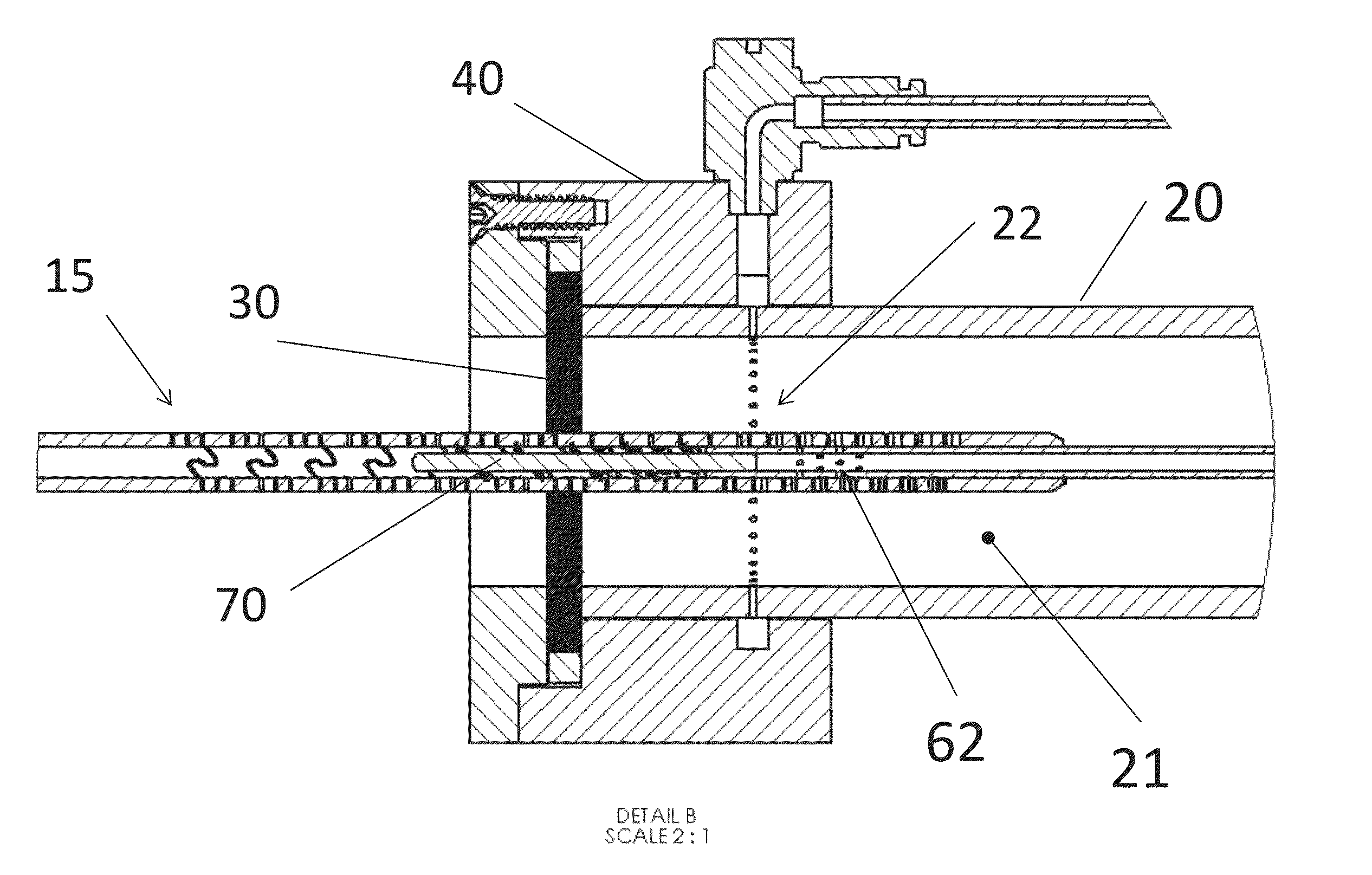
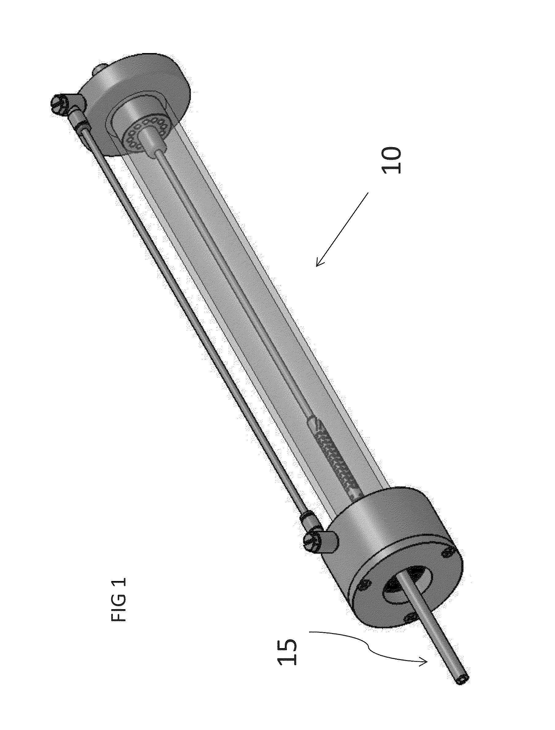
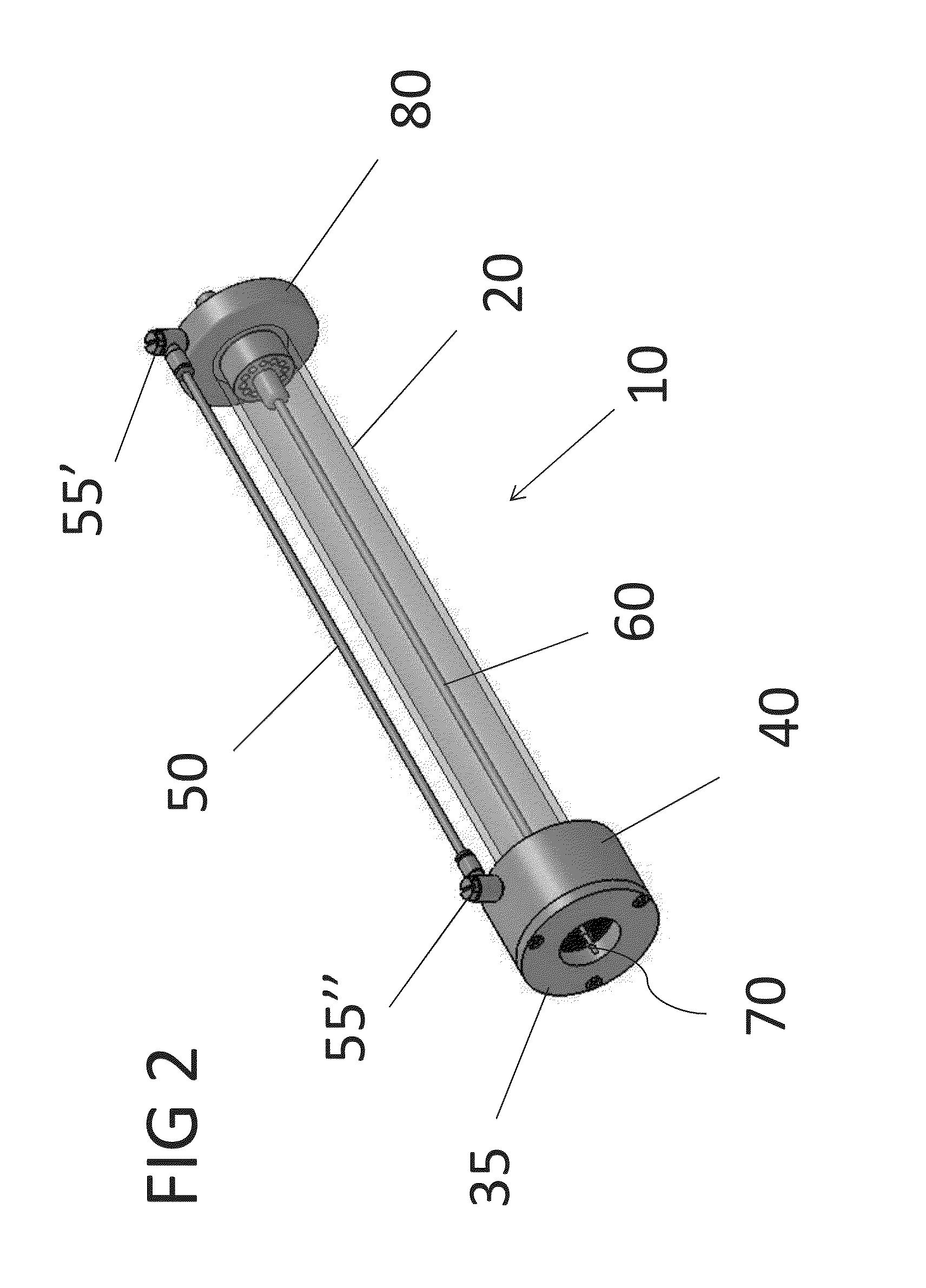
[0098]As used herein the term “tubular” refers to a hollow body having a cross section of one or more sides.

[0099]As used herein the term “lavage fluid” refers to the cleansing, or cleaning, fluid used for flushing and / or irrigating a medical tool, device or instrument.

[0100]The present invention is specifically related to an apparatus and process for cleaning surgical instruments by flushing the cannulated instrument with a lavage fluid for debris removal. More particularly, the present invention is directed to an apparatus for forcing a lavage, or cleaning, solution through a cannulated surgical instrument, such as a reamer, to remove gross debris from surgery. The apparatus utilizes a fluid lavage fluid system or other source of pressurized lavage fluid solution to provide the motive power required for forcing a lavage fluid through the cannula of a cannulated instrument. In a preferred embodiment, the present invention includes pressurized tanks for delivering a stead...


PUM


Abstract

An apparatus for cleaning cannulated surgical tools comprises a hollow body with lavage fluid holes at a first end along with a brush adaptor affixed to the hollow body. An inlet adaptor is affixed, having to a second end of the hollow body. A body hub, consisting of inlet channel and drain channel is in liquid communication with an inner lavage fluid tube. A lavage connection tube is in liquid communication with the hollow body at the brush adaptor and through the upper connecting lavage fluid orifice. An inner lavage fluid tube, having an inner channel, extends within the hollow body with a distal end in liquid communication at a proximal end of the inner channel within the inlet adaptor. There are multiple spray openings proximate the distal end of the inner lavage fluid connection tube and a tube brush is dimensioned to fit within the inner channel. The apparatus can be provided with attachment members and combined with a reservoir to make the unit self-contained.

Description

FIELD OF THE INVENTION[0001]The present invention is in the field of cleaning and decontaminating surgical instruments and other medical devices used in healthcare facilities.BACKGROUND OF THE INVENTION[0002]Medical procedures often involve the use of cannulated flexible shafts, endoscopes and other elongated instruments which are inserted through surgical openings. These medical instruments are relatively expensive products and must be used multiple times. Accordingly, such devices of necessity must be cleaned and sterilized repeatedly. Such instruments typically include long narrow cannulas through which surgical implements and other devices are passed in a surgical procedure. Both the interior and exterior of such cannulas thus are subject to contamination by bodily fluids and materials and must be cleaned carefully before reuse. If they are not thoroughly cleaned prior to disinfection and sterilization, surgical debris can be passed to another patient leading to infection or oth...

Claims


Application Information

Patent Timeline
Patent Type & Authority Applications(United States)
IPC IPC(8): A61B19/00
CPCA61B2019/343A61B19/34A61B90/70A61B2090/701
Inventor KRAUSE, WILLIAM R
Owner FLEX TECH
Why Eureka
Try Eureka