Method and apparatus for providing percussive ventilation therapy to a patient airway

a technology for providing percussive ventilation and patient airways, which is applied in the direction of medical devices, medical atomizers, medical devices, etc., can solve the problems of reducing the body's ability to remove mucus, increasing mucus production, and substantial mortality and morbidity, so as to reduce complexity, facilitate mucus mobilization, and effective system and method

Pending Publication Date: 2021-07-08
BOUGATEF ADEL
View PDF0 Cites 0 Cited by
  • Summary
  • Abstract
  • Description
  • Claims
  • Application Information

AI Technical Summary

Benefits of technology

[0013]The present invention provides an effective system and method for facilitating mobilization of mucus using percussive ventilations, with reduced complexity and hence lower cost. It comprises a source of pressurized gas from a Driver unit which is supplied at constant pressure to a Patient Interface Device. The Patient Interface Device preferably comprises a disposable part and reusable part: the reusable part preferably employs an air interrupter valve and the disposable part preferably employs a Venturi system.
[0015]An object of the invention is to preferably provide an efficacious, continuous, high frequency percussive breathing therapy that does not rely on expensive consumables. Another object of the invention is to preferably reduce the bulk, noise, and complexity of the Driver unit to lower manufacturing costs. Yet another object of the invention is to preferably reduce the power consumption of the system to permit convenient transport and battery powered operation. A further object of the invention is to preferably lower maintenance and service costs. Another object of the invention is to preferably provide a simple, convenient, and easy to use system.
[0016]Another object of the invention is to preferably provide an efficacious, continuous, Adaptive Dynamic Subtidal ventilation therapy. Another object of the invention is to preferably reduce the bulk, noise, and reduce the power consumption of the system to permit convenient transport and battery powered operation. A further object of the invention is to preferably lower maintenance and service costs. Another object of the invention is to preferably provide a simple, convenient, and easy to use system.

Problems solved by technology

Illness such as Chronic Obstructive Pulmonary Disease (COPD) are indications of damage to the respiratory surfaces, causing inflammation (which affect the cilia's ability to mobilize secretions), increased mucus production, and swollen passageways which restrict airflow, further reducing the body's ability to remove mucus.
Acute and chronic lung diseases management remains an important health problem with substantial mortality and morbidity.
Unfortunately, there are few effective devices able to deliver percussive ventilation therapy, and those which are proven effective are expensive.
However, the Driver Unit employs a pneumatic air interrupter valve which requires high pressure (up to 40 psi) to reliably provide a high-frequency percussive effect, resulting in a large, noisy Driver unit that is power inefficient, must be operated from mains, and is costly to manufacture.
However, any approach to generate percussive ventilation which employs an air interrupter valve in a distal Driver feeding pulses of air to a proximal Patient Interface Device will suffer from lessening of the percussive effect caused by both the compressibility and inertia of the air contained within the hose from the distal Driver unit to the Patient Interface Device, and also dampening effects due to the elastic compliance of the hose itself.
In addition, the air interrupter valve must endure millions of cycles of operation during the Driver unit lifetime, is prone to wear and requires expensive maintenance to replace.
However, as in the case of the pneumatic air interrupter valve, but also this requires high working pressure in the Driver Unit (up to 40 psi, with associated bulk, noise, and low efficiency), whereas the jet pressure applied to the Venturi inlet is typically less than 10 psi.

Method used


Image

  • Method and apparatus for providing percussive ventilation therapy to a patient airway
  • Method and apparatus for providing percussive ventilation therapy to a patient airway
  • Method and apparatus for providing percussive ventilation therapy to a patient airway

Examples


Embodiment Construction

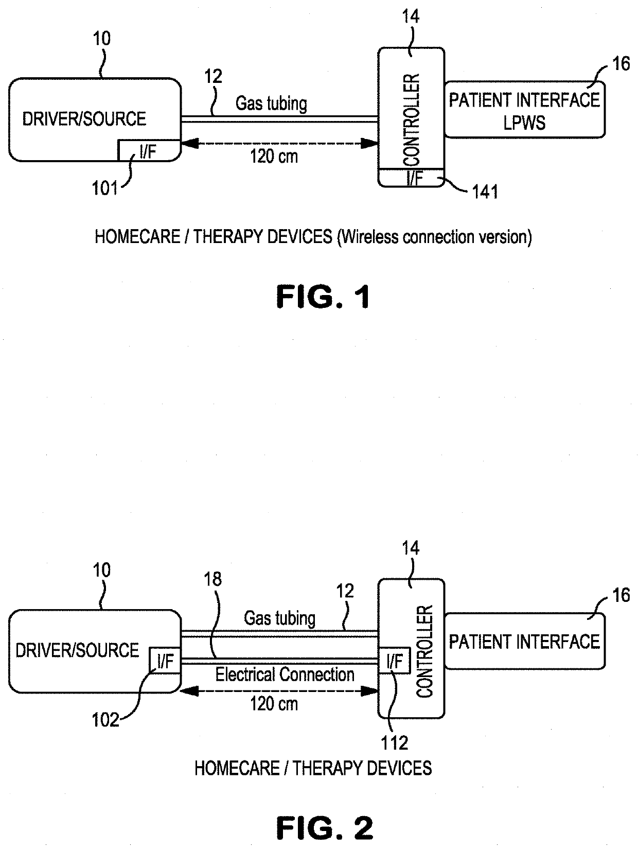
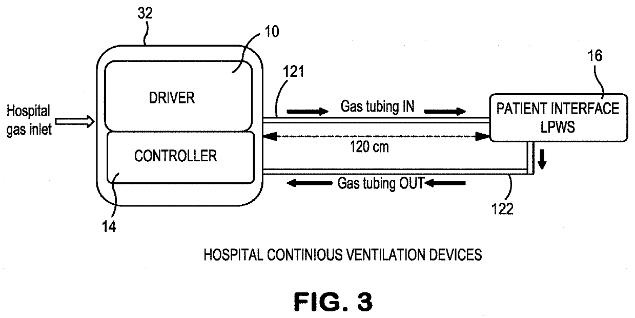
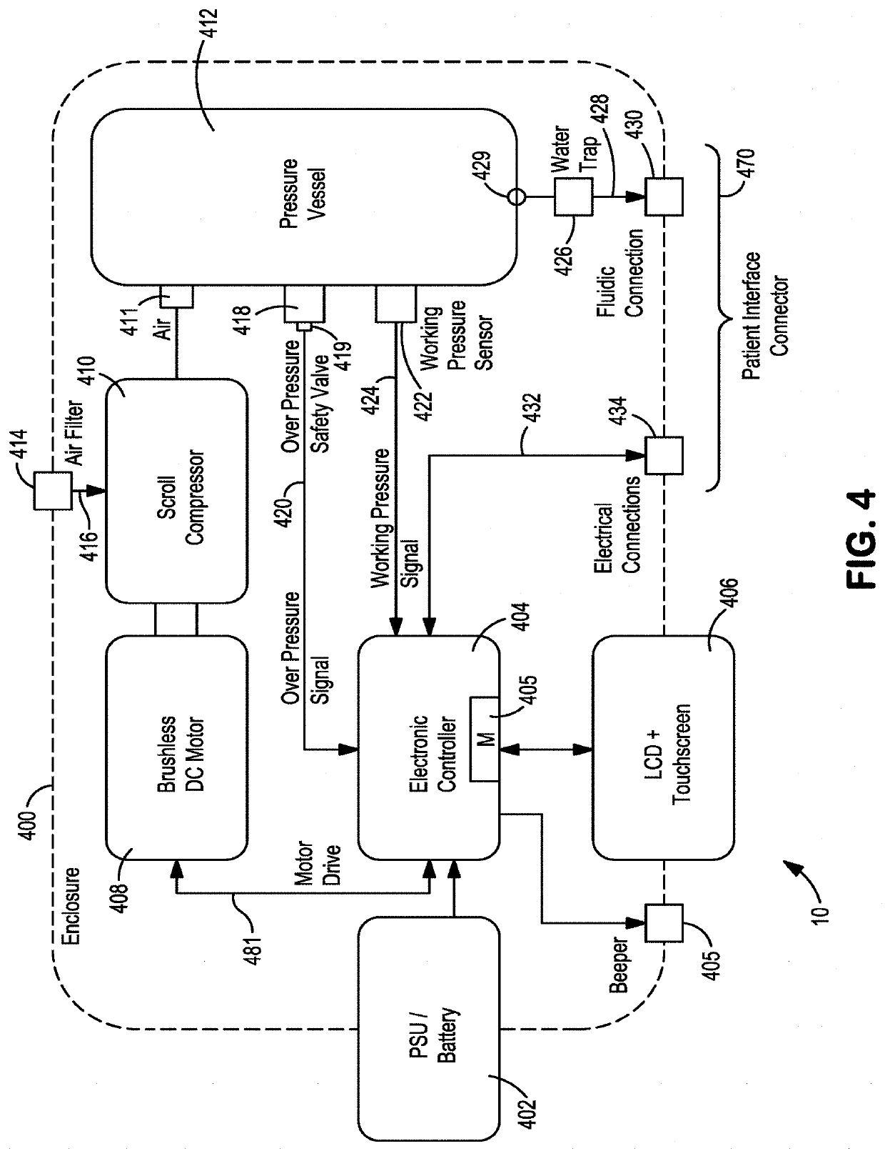
[0050]In overview, the present embodiments provide a Home Therapy and / or Hospital Therapy apparatus and method whereby percussive ventilation therapy is provided to at least one patient's airway. While the present invention has particular applicability to human patients, the preferred embodiments may be of use to any animal patient(s) as well.

[0051]“Adaptive Dynamic Subtidal Ventilation” (ADSV) technology in this specification may include, but is not limited to, one or more of, or any combination of structure and / or function whereby the Patient Interface Device is: Adaptive because the delivered flow will permanently adapt to patient physiologic parameters; Dynamic because it will have a waveform that brings energy to recruit the airways and will affect the hemodynamic (the permanent change in flow / pressure / volume is dynamic); Subtidal because it will deliver small volumes called subtidal volumes; and Ventilation because it will affect gas exchange, oxygenate, and ventilate.

[0052]A ...


PUM


Abstract

Method and apparatus for providing percussive ventilation therapy to a patient airway preferably includes at least one driver unit configured to provide pressurized, non-pulsate gas. At least one patient interface device preferably has structure configured to (i) receive the pressurized, non-pulsate gas from the at least one driver unit and transform it into a pulsed and pressurized gas, and (ii) supply at least one sub tidal volume of pulsed and pressurized gas to a patient through a patient connection orifice. At least one flexible tube is preferably configured to provide pressurized, non-pulsate gas from the at least one driver unit to the at least one patient interface device. Preferably, at least one portion of the patient interface device is disposable, and another portion may be reusable. Preferably, the invention uses Adaptive Dynamic Subtidal Ventilation technology.

Description

CROSS REFERENCE TO RELATED APPLICATIONS[0001]This application is a continuation-in-part (CIP) application of U.S. application Ser. No. 15 / 656,818, filed on Jul. 21, 2017, which claims priority to U.S. Provisional Patent Appin. No. 62 / 369,954, filed Aug. 2, 2016, the entire contents of which are incorporated herein by reference.BACKGROUND OF THE INVENTION[0002]The respiratory airways employ tiny hairs, called motile cilia, which beat in coordinated waves to facilitate removal of pulmonary mucus by directing it to the back of the throat. Illness such as Chronic Obstructive Pulmonary Disease (COPD) are indications of damage to the respiratory surfaces, causing inflammation (which affect the cilia's ability to mobilize secretions), increased mucus production, and swollen passageways which restrict airflow, further reducing the body's ability to remove mucus.[0003]With the ageing populations, the prevalence of lung disease is increasing, particularly in those countries with a high smokin...

Claims


Application Information

Patent Timeline
Patent Type & Authority Applications(United States)
IPC IPC(8): A61M16/12A61M16/00A61M16/20
CPCA61M16/127A61M16/0096A61M16/0012A61M16/204A61M16/205A61M11/005A61M11/06A61M16/0051A61M16/0808A61M16/0816A61M16/14A61M16/16A61M2016/0021A61M2016/0027A61M2016/0036A61M2016/1025A61M2202/0208A61M2205/17A61M2205/18A61M2205/3331A61M2205/3368A61M2205/3553A61M2205/3592A61M2205/42A61M2205/505A61M2205/52A61M2205/581A61M2205/583A61M2205/7545A61M2205/8206A61M2205/84A61M16/0006A61M16/0063A61M16/1065A61M16/1095A61M16/201A61M16/202A61M16/209A61M16/024
Inventor BOUGATEF, ADEL
Owner BOUGATEF ADEL
Why Eureka
Try Eureka