Fuel leak detection system for use in a turbine enclosure

a technology for turbine engines and leak detection systems, which is applied in the direction of machines/engines, fluid-tightness measurement, instruments, etc., can solve the problem of difficult accurate fuel leak detection

Active Publication Date: 2015-10-29
GENERAL ELECTRIC CO
View PDF7 Cites 23 Cited by
  • Summary
  • Abstract
  • Description
  • Claims
  • Application Information

AI Technical Summary

Problems solved by technology

However, accurate fuel leak detection may be difficult if leaked fuel is

Method used


Image

  • Fuel leak detection system for use in a turbine enclosure
  • Fuel leak detection system for use in a turbine enclosure
  • Fuel leak detection system for use in a turbine enclosure

Examples


Embodiment Construction

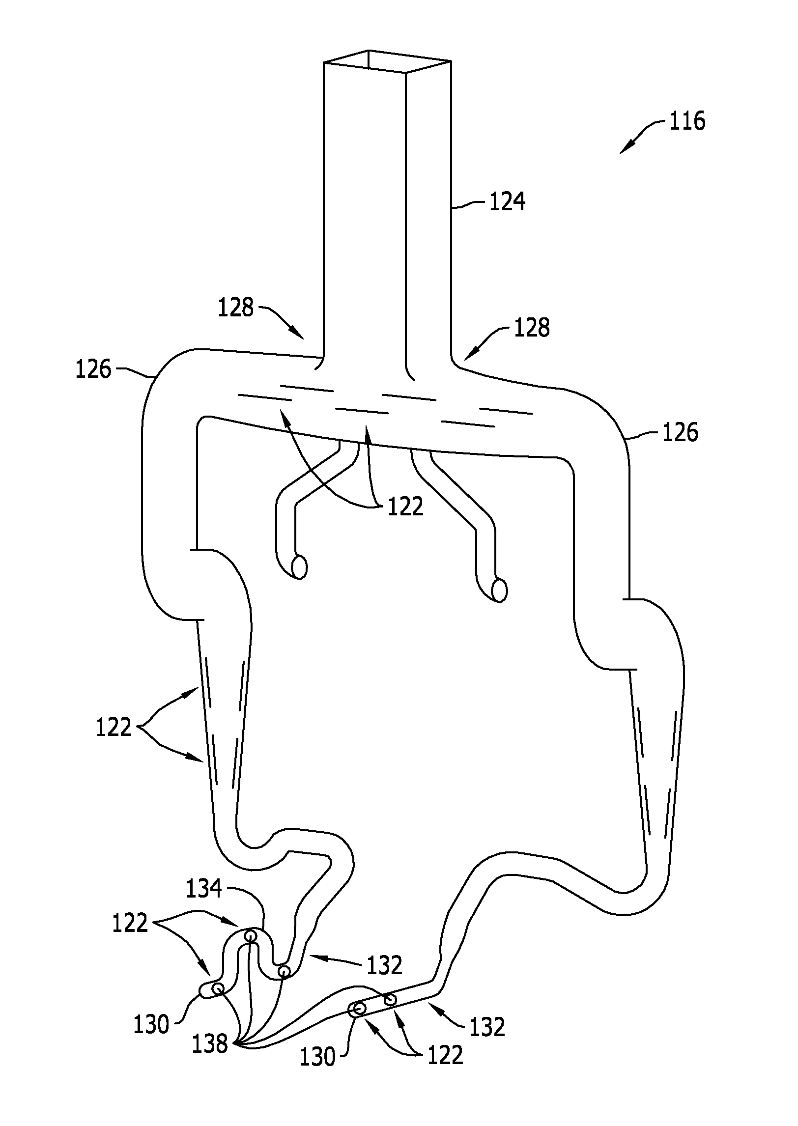
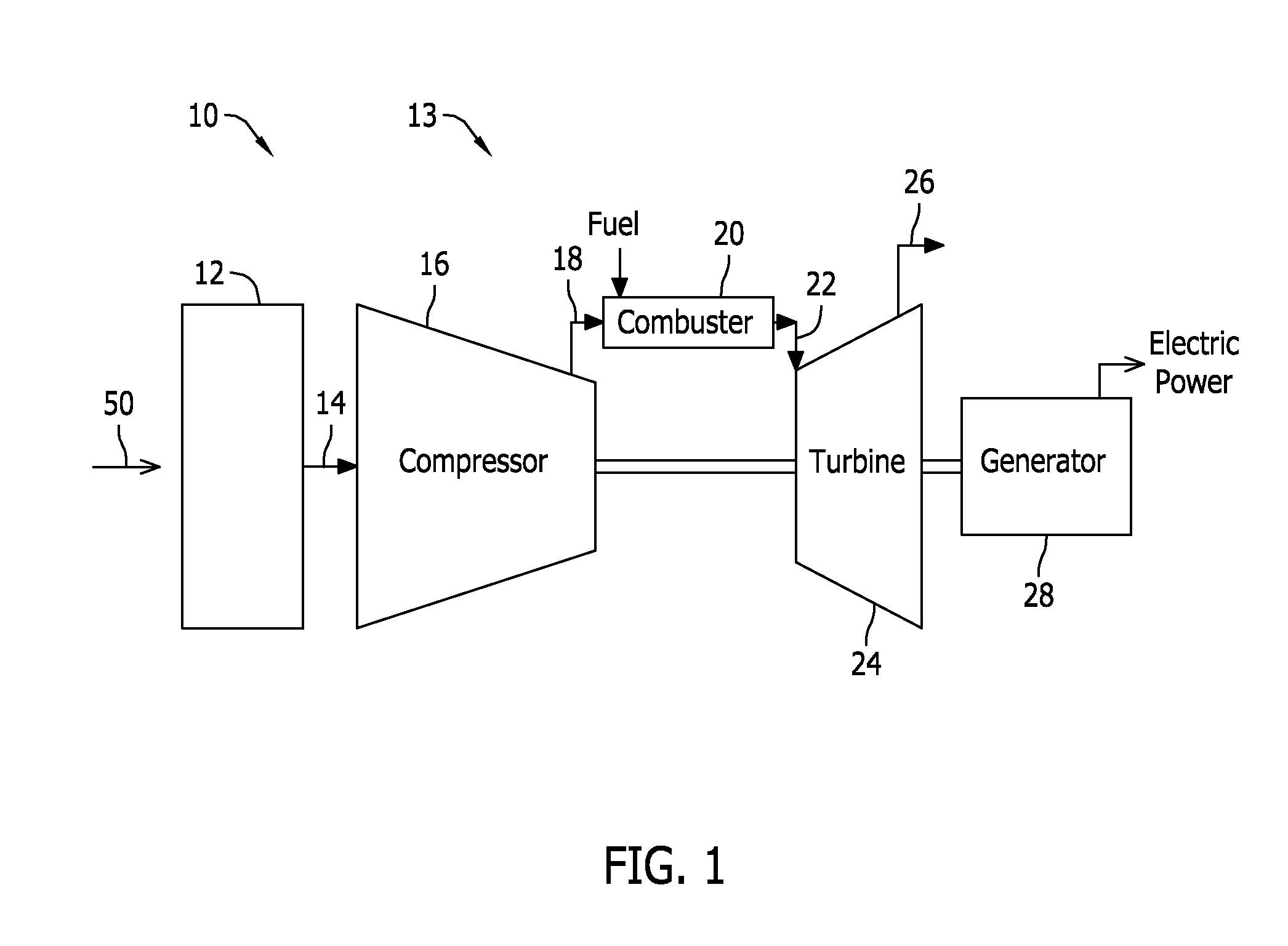
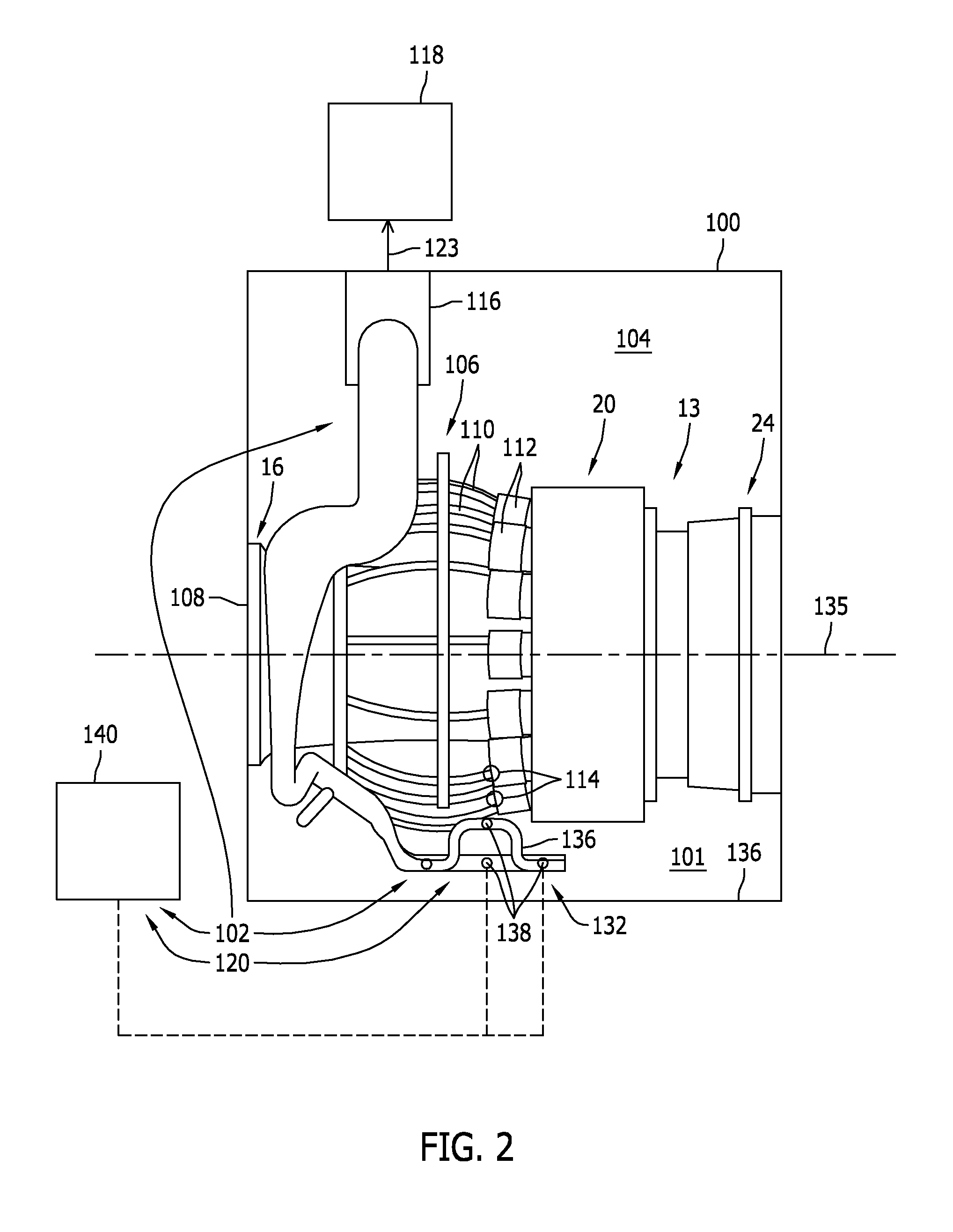
[0010]Embodiments of the present disclosure relate to fuel leak detection systems for use in a gas turbine engine enclosure. In the exemplary embodiment, the fuel leak detection system includes a ventilation duct having a plurality of openings defined therein such that air is drawn into the ventilation duct through the openings. At least some known fuels used in gas turbine engines are heavier than air. As such, the ventilation duct includes an extended portion positioned within a bottom portion of the enclosure such that fuel potentially accumulating in the bottom portion of the enclosure is drawn through openings in the extended portion along with the flow air. The fuel leak detection system also includes a sensor system coupled in flow communication with the flow of air channeled through the ventilation duct. The sensor system detects the presence of fuel in the air. In some embodiments, fuel detection probes of the sensor system are positioned within the extended portion of the ...


PUM


Abstract

A fuel leak detection system for use in a turbine enclosure is provided. The system includes a ventilation duct extending through an interior cavity of the turbine enclosure such that an extended portion of the ventilation duct is positioned within a bottom portion of the turbine enclosure. The ventilation duct includes a plurality of openings configured to allow air from within the turbine enclosure to be drawn into the ventilation duct through the plurality of openings. The system also includes a sensor system coupled in flow communication with the air drawn into the ventilation duct, the sensor system configured to detect fuel in the air.

Description

BACKGROUND[0001]The present disclosure relates generally to turbine engines and, more specifically, to systems and methods of fuel leak detection in turbine engine enclosures.[0002]Gas turbine engines are used as a power source within a variety of applications. To protect the engine from the environment, and to shield the surrounding environment from the gas turbine engine, at least some known gas turbine engines are housed within an engine assembly enclosure that includes an inlet area, an exhaust area, such as an ventilation duct, and an engine area that extends between the inlet area and the exhaust area. For example in a power generation facility where the gas turbine engine is used as a power source for an electrical generator, the engine may be housed inside an enclosure that facilitates reducing noise and heat generated during engine operation.[0003]Current regulatory codes may require that an engine control system provide an alarm to an operator and / or automatically stop the...

Claims


Application Information

Patent Timeline
IPC IPC(8): G01M3/04G01M15/14G01M3/16
CPCG01M3/04G01M15/14G01M3/16
Inventor KONATHAM, RAJESH REDDYWOLF, LEN ALANMERCHANT, LAXMIKANTALAGAPPAN, RAJAKUMARSHANKAR, LAKSHMI BETTADAPURA
Owner GENERAL ELECTRIC CO
Why Eureka
Try Eureka