Methods for location identification of renewable energy systems

a renewable energy system and location identification technology, applied in the field of methods for location identification of renewable energy systems, can solve the problems of user input, human error, and the adoption of distributed renewable energy projects

Inactive Publication Date: 2015-10-29
LOCUS ENERGY
View PDF7 Cites 9 Cited by
  • Summary
  • Abstract
  • Description
  • Claims
  • Application Information

AI Technical Summary

Benefits of technology

[0010]According to another embodiment of the present invention, a computer processor implemented method of identifying the location of a renewable energy system is provided, the method comprising the steps of; providing a location-unknown renewable energy system having production data; storing the production data in a computer processor; filtering the production data day by day for favorable weather conditions by a computer processor to provide filtered production data for each filtered day; identifying and saving the start of production, peak of production and end of production for each filtered day in a computer processor; calculating solar noon for each filtered day by a computer processor; calculating longitude bias for each filtered day by a computer processor according to an equation of time and the peak of production; calculating skew of production by a computer processor according to the start of production, peak of production and end of production for each filtered day; calculating longitude for one location-unknown renewable energy system by a computer processor according to the longitude bias and skew of production for each filtered day; setting the longitude for the location-unknown renewable energy system to become a location-known renewable energy system that becomes part of a set of location-known renewable energy systems.

Problems solved by technology

One of the greatest obstacles to adoption of distributed renewable energy projects is the ability to efficiently monitor and analyze a fleet of systems.
While geospatial analytics have proven effective in monitoring, location among other variables describing renewable energy systems and environmental sensors are user inputs and subject to human error.
When systems are incorrectly located it is difficult to employ analytical algorithms reliant upon geospatial data due to the errors caused in systems within the incorrectly located region.
It is difficult to accurately monitor and analyze a fleet of projects with these errors, thus the need for methodology for correctly identifying the location of incorrectly located renewable energy systems and environmental sensors.
Due to the separation, interested parties may have partially complete or incorrect information about these systems.
This separation can limit the benefits associated with monitoring and analyzing renewable energy projects, thus the need for methodology to accurately locate the projects and environmental sensors.

Method used


Image

  • Methods for location identification of renewable energy systems
  • Methods for location identification of renewable energy systems
  • Methods for location identification of renewable energy systems

Examples


Embodiment Construction

[0026]The following detailed description is of the best currently contemplated modes of carrying out the invention. The description is not to be taken in a limiting sense, but is made merely for the purpose of illustrating the general principles of the invention, since the scope of the invention is best defined by the appended claims.

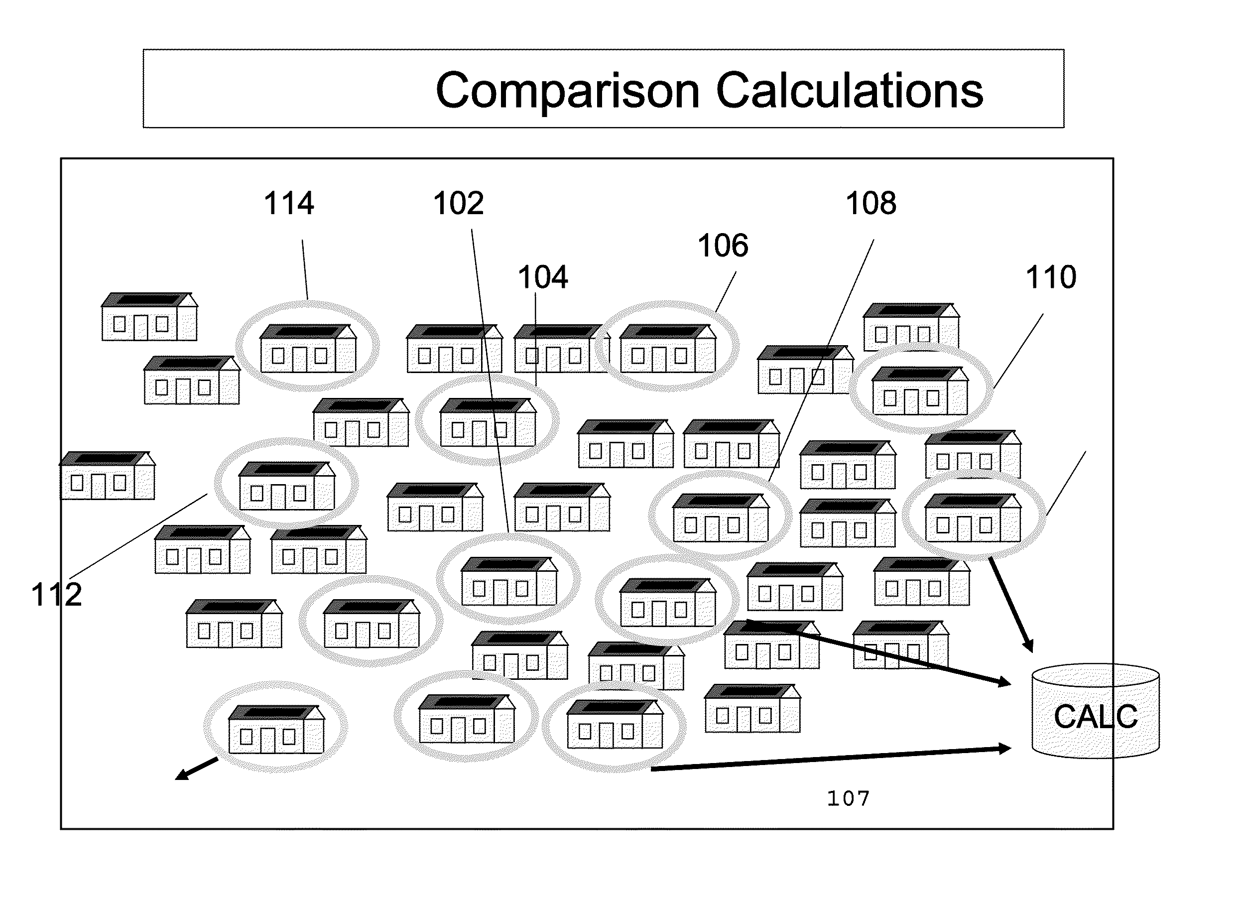
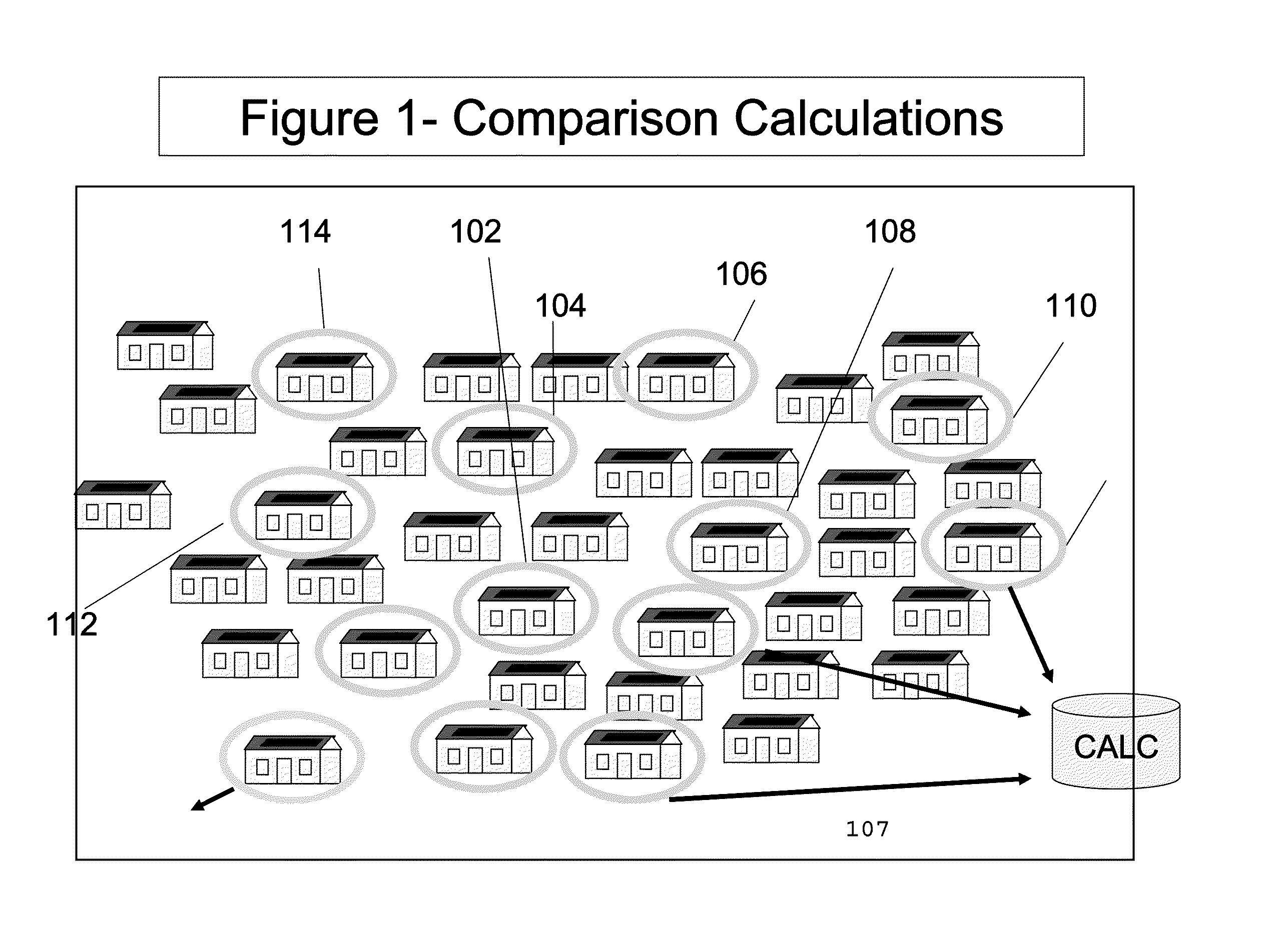
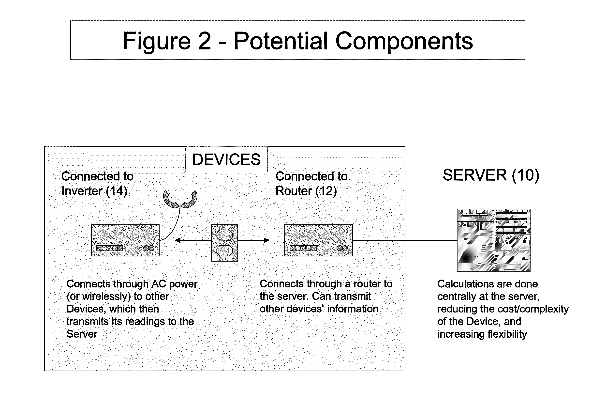
[0027]FIGS. 1-5 provide examples of a monitored renewable energy system (more specifically a photovoltaic array solar panel also referred to herein as a solar photovoltaic system or solar powered system) from which information may be obtained. According to the example shown, there is a server 10 and at least one monitored renewable energy system (e.g. 102, 104, 106, 108, 110, 112) which is provided to a user or consumer. There may be at least one data server (10), at least one generation monitoring device (16) in communication with the monitored renewable energy system (at premise monitored renewable energy system (30)) and at least one communication no...


PUM


Abstract

A method of identifying the location of a renewable energy system; providing a location-unknown renewable energy system having production data; filtering production data day by day for favorable weather conditions to provide filtered production data for each filtered day; identifying and saving the start of production, peak of production and end of production for each filtered day; calculating solar noon for each filtered day; calculating longitude bias for each filtered day according to an equation of time and the peak of production; calculating skew of production according to the start of production, peak of production and end of production for each filtered day; calculating longitude for one location-unknown renewable energy system according to the longitude bias and skew of production for each filtered day; setting longitude for location-unknown renewable energy system to become a location-known renewable energy system that becomes part of a set of location-known renewable energy systems.

Description

[0001]This application is a divisional application of Ser. No. 13 / 623,232 filed Sep. 20, 2012 entitled, “METHODS FOR LOCATION IDENTIFICATION OF RENEWABLE ENERGY SYSTEMS” which claims priority to provisional patent application No. 61 / 576,315 filed Dec. 15, 2011 entitled “Methods for Location Identification of Renewable Energy Systems and Environmental Sensors from Energy Production and Sensor Measurements,” which is incorporated herein by reference.[0002]One of the greatest obstacles to adoption of distributed renewable energy projects is the ability to efficiently monitor and analyze a fleet of systems. There currently exist several monitoring solutions with analytics based on geospatial relationships. While geospatial analytics have proven effective in monitoring, location among other variables describing renewable energy systems and environmental sensors are user inputs and subject to human error. When systems are incorrectly located it is difficult to employ analytical algorithms...

Claims


Application Information

Patent Timeline
Patent Type & Authority Applications(United States)
IPC IPC(8): G01V99/00
CPCG01V99/00G06Q50/06
Inventor KERRIGAN, SHAWNHERZIG, MICHAELWILLIAMS, MATTHEW
Owner LOCUS ENERGY
Why Eureka
Try Eureka