Unmanned aerial vehicle system and method for dynamically positioning ground moving target

A technology for moving targets and unmanned aerial vehicles, which is applied in the field of UAV systems for dynamic positioning of ground moving targets, and can solve problems such as difficult engineering implementation, inability to realize dynamic positioning and target behavior prediction, and low calculation accuracy of fixed target positions

Active Publication Date: 2014-02-26
CHINA ACAD OF AEROSPACE AERODYNAMICS
View PDF3 Cites 89 Cited by
  • Summary
  • Abstract
  • Description
  • Claims
  • Application Information

AI Technical Summary

Problems solved by technology

Although this method can describe the information in the field of view at the same time in a relatively large degree, but because multiple targets do not move at the same time or in the same direction in practical applications, there is a large lag in information acquisition in this method
[0007] In addition, there are other methods that are only at the theoretical stage, such as the target positioning method based on image matching, which has high accuracy but poor practicality, and has not yet been engineered; the positioning method of dual UAVs under the constraint of communication distance and the rendezvous of two points in space are unmanned. Machine positioning method, the principle is simple, the error introduces fewer elements, but it lacks operability
These methods are difficult to implement in engineering, and in the actual application process, they cannot locate moving targets on the ground in real time, and the calculation accuracy of fixed target positions is not high, and they cannot realize dynamic positioning and target behavior prediction.

Method used


Image

  • Unmanned aerial vehicle system and method for dynamically positioning ground moving target
  • Unmanned aerial vehicle system and method for dynamically positioning ground moving target
  • Unmanned aerial vehicle system and method for dynamically positioning ground moving target

Examples


Embodiment Construction

[0052] In order to make the object, technical solution and advantages of the present invention clearer, the implementation manner of the present invention will be further described in detail below in conjunction with the accompanying drawings.

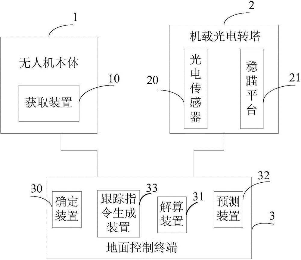
[0053] see figure 2 , the embodiment of the present invention provides an unmanned aerial vehicle system for dynamic positioning of ground moving targets. Carrying a photoelectric turret 2 , a ground control terminal 3 with a determining device 30 , a tracking instruction generating device 33 , a calculating device 31 and a predicting device 32 .

[0054] Wherein, the obtaining device 10 is used to obtain the three-axis attitude angle, longitude, and latitude of the UAV body and the relative height between the UAV body and the ground moving target to be positioned. In practice, the three-axis attitude angle of the UAV body is obtained by the three-axis attitude sensor of the UAV body; the longitude and latitude of the UAV body are ob...


PUM


Abstract

The invention discloses an unmanned aerial vehicle system and a method for dynamically positioning a ground moving target, belonging to the fields of unmanned aerial vehicle system application and the like. The unmanned aerial vehicle system comprises an unmanned aerial vehicle body, a vehicle-mounted photoelectric rotating tower and a ground control terminal, wherein the unmanned aerial vehicle body comprises an acquisition device, the vehicle-mounted photoelectric rotating tower comprises a photoelectric sensor and a sight-stabilizing platform, and the ground control terminal comprises a determining device, a trace command generating device, a resolving device and a predicting device. According to the technical scheme provided by the invention, geographical coordinate information including latitude, longitude and the like of a tracked ground moving target can be output in real time, the original geographical coordinate information can be accurately and quickly fitted, the moving trend of the ground moving target can be predicted and evaluated, and the original geographical coordinate information can be screened to realize display and prediction of the track of the moving target; the positioning accuracy acquired by the unmanned aerial vehicle system and the method approaches that of static positioning and can meet requirements for initial alignment of weapons including artilleries and the like, and the probability of fusion processing of an unmanned aerial vehicle intelligence system and an entire-army intelligence gathering network is provided.

Description

technical field [0001] The invention relates to the fields of unmanned aerial vehicle system application, photoelectric stabilization, image processing, photogrammetry, and telemetry data processing, and in particular to an unmanned aerial vehicle system and method for dynamic positioning of ground moving targets. Background technique [0002] During the use of drones, image reconnaissance is the main focus. With the need for target positioning, such as guiding fighter jets or missiles for fire strikes, correcting artillery targeting parameters, etc., UAVs begin to have target positioning capabilities. [0003] In the prior art, the realization method of target positioning is as follows: the wireless link receives the spatial position of the UAV and the camera parameters of the optical axis stabilization platform, and after "freezing" the reconnaissance image at a certain moment, the target positioning calculation and the turret Whether the servo mechanism is still tracking...

Claims


Application Information

Patent Timeline
Patent Type & Authority Applications(China)
IPC IPC(8): G01C21/00
CPCG05D1/12
Inventor 杨勇周乃恩吴洋
Owner CHINA ACAD OF AEROSPACE AERODYNAMICS
Why Eureka
Try Eureka