3D Printing Part Removal and Interface For A 3D Printing Vending Machine

Active Publication Date: 2015-11-05
VIRGINIA TECH INTPROP INC
View PDF2 Cites 26 Cited by
  • Summary
  • Abstract
  • Description
  • Claims
  • Application Information

AI Technical Summary

Benefits of technology

[0010]In yet another embodiment, the present invention provides a printer that is highly modular, reliable, and portable.
[0011]In another embodiment, the present invention provides an ejection mechanism in which completed parts may be automatically removed from the build platform after

Problems solved by technology

For example, current designs lack portability as a result of being designed to be operational in stationary locations.
Current designs are also unreliable.
It is not uncommon to have print jams caused by clogged extruders, unreliable heating elements, improper l

Method used


Image

  • 3D Printing Part Removal and Interface For A 3D Printing Vending Machine
  • 3D Printing Part Removal and Interface For A 3D Printing Vending Machine
  • 3D Printing Part Removal and Interface For A 3D Printing Vending Machine

Examples


Embodiment Construction

[0031]Detailed embodiments of the present invention are disclosed herein; however, it is to be understood that the disclosed embodiments are merely exemplary of the invention, which may be embodied in various forms. Therefore, specific structural and functional details disclosed herein are not to be interpreted as limiting, but merely as a representative basis for teaching one skilled in the art to variously employ the present invention in virtually any appropriately detailed method, structure or system. Further, the terms and phrases used herein are not intended to be limiting, but rather to provide an understandable description of the invention.

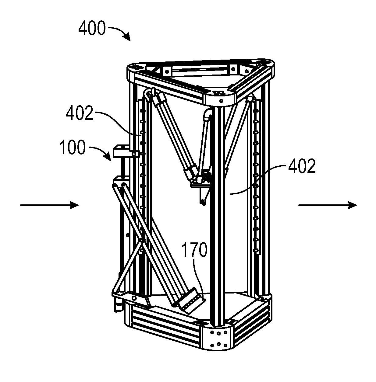
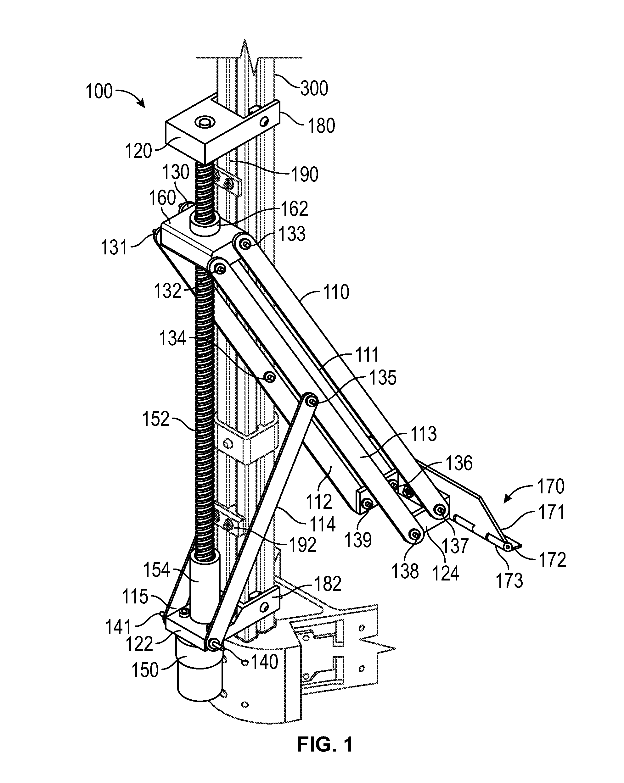
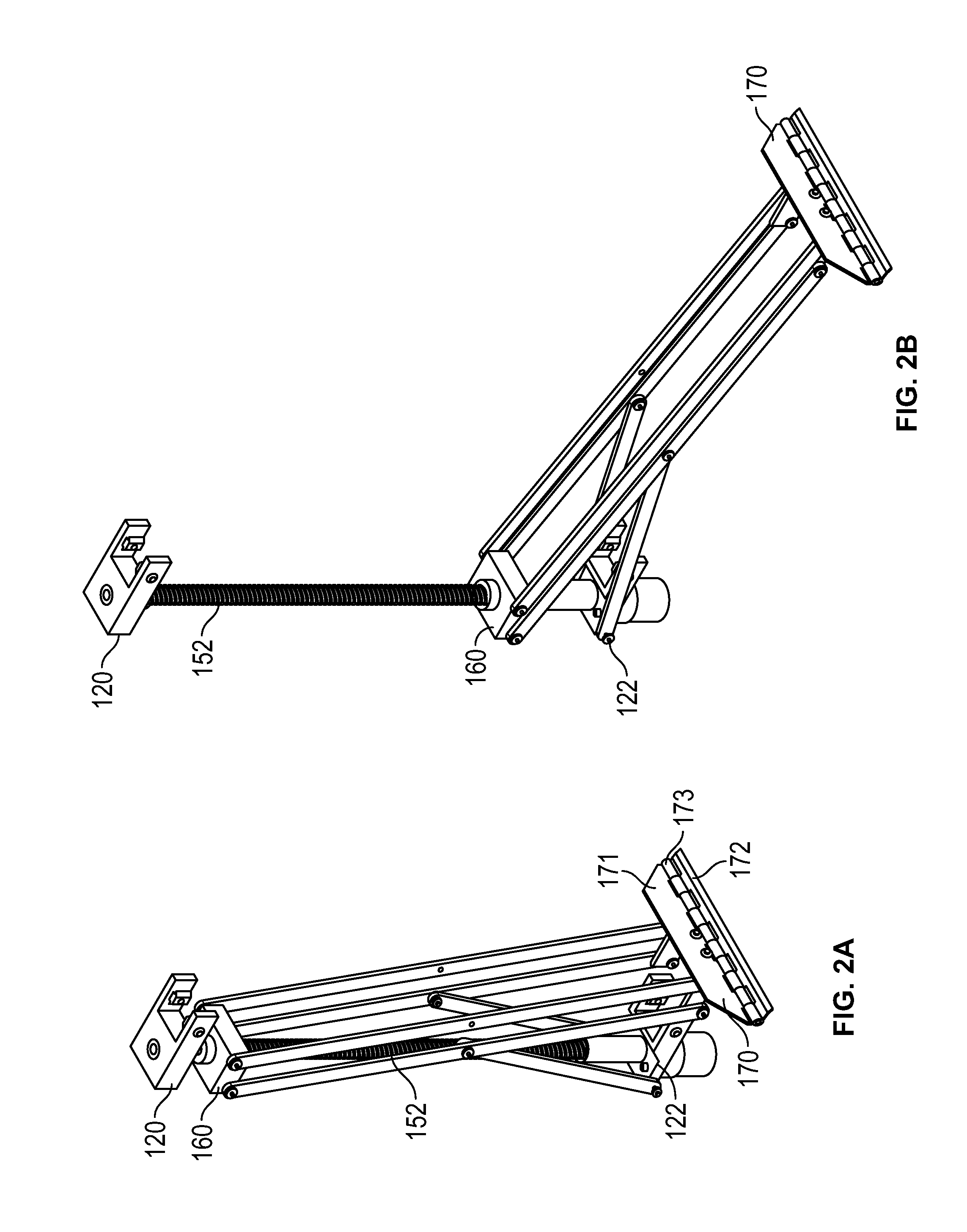
[0032]In one embodiment, as shown in FIG. 1, the present invention provides an ejection mechanism or assembly 100 for the automatic removal of a part created through the use of additive manufacturing (3D printing). Ejection mechanism 100 may mounted to post 300 and consist of compact, parallel kinematic linkage arms 110-115 that may be spac...


PUM

PropertyMeasurementUnit
Coloraaaaaaaaaa
Areaaaaaaaaaaa
Distanceaaaaaaaaaa

Abstract

The present invention concerns a system and method for fabricating a three-dimensional object. A build platform is provided that defines a build area and includes a print bed within the build area. Also provided is an extruder that extrudes build material. An ejector having at least one arm that has at least two opposing ends is used to remove the printed object. The first end of the ejector is adapted to travel in a vertical direction and the second end is adapted to travel in a horizontal direction. A scraper portion extends horizontally, parallel to the print bed from a retracted position to an extended position when the first end travels in a vertical direction towards the print bed.

Description

RELATED APPLICATIONS[0001]This application claims the benefit of U.S. Provisional Application No. 61 / 987942 filed May 2, 2014 and the benefit of U.S. Provisional Application No. 61 / 987936 filed May 2, 2014 both of which are herein incorporated by reference.STATEMENT REGARDING FEDERALLY SPONSORED RESEARCH & DEVELOPMENT[0002]Not applicable.[0003]INCORPORATION BY REFERENCE OF MATERIAL SUBMITTED ON A COMPACT DISC[0004]Not applicable.BACKGROUND OF THE INVENTION[0005]The present invention relates to the field of additive manufacturing (3D printing). While there are a number of acceptable 3D printer designs currently, there remains room for improvement. For example, current designs lack portability as a result of being designed to be operational in stationary locations.[0006]Current designs are also unreliable. It is not uncommon to have print jams caused by clogged extruders, unreliable heating elements, improper layer height calibration and failures in the movement of the printing head c...

Claims


Application Information

Patent Timeline
IPC IPC(8): B29C67/00
CPCB29C67/0051B29L2009/00B33Y30/00B33Y40/00B29C64/35B29C64/25B29C64/227B29C64/106
Inventor KLINE, KEVIN D.
Owner VIRGINIA TECH INTPROP INC
Why Eureka
Try Eureka