Apparatus for channelling cooking fumes
- Summary
- Abstract
- Description
- Claims
- Application Information
AI Technical Summary
Benefits of technology
Problems solved by technology
Method used
Image

Examples
first embodiment
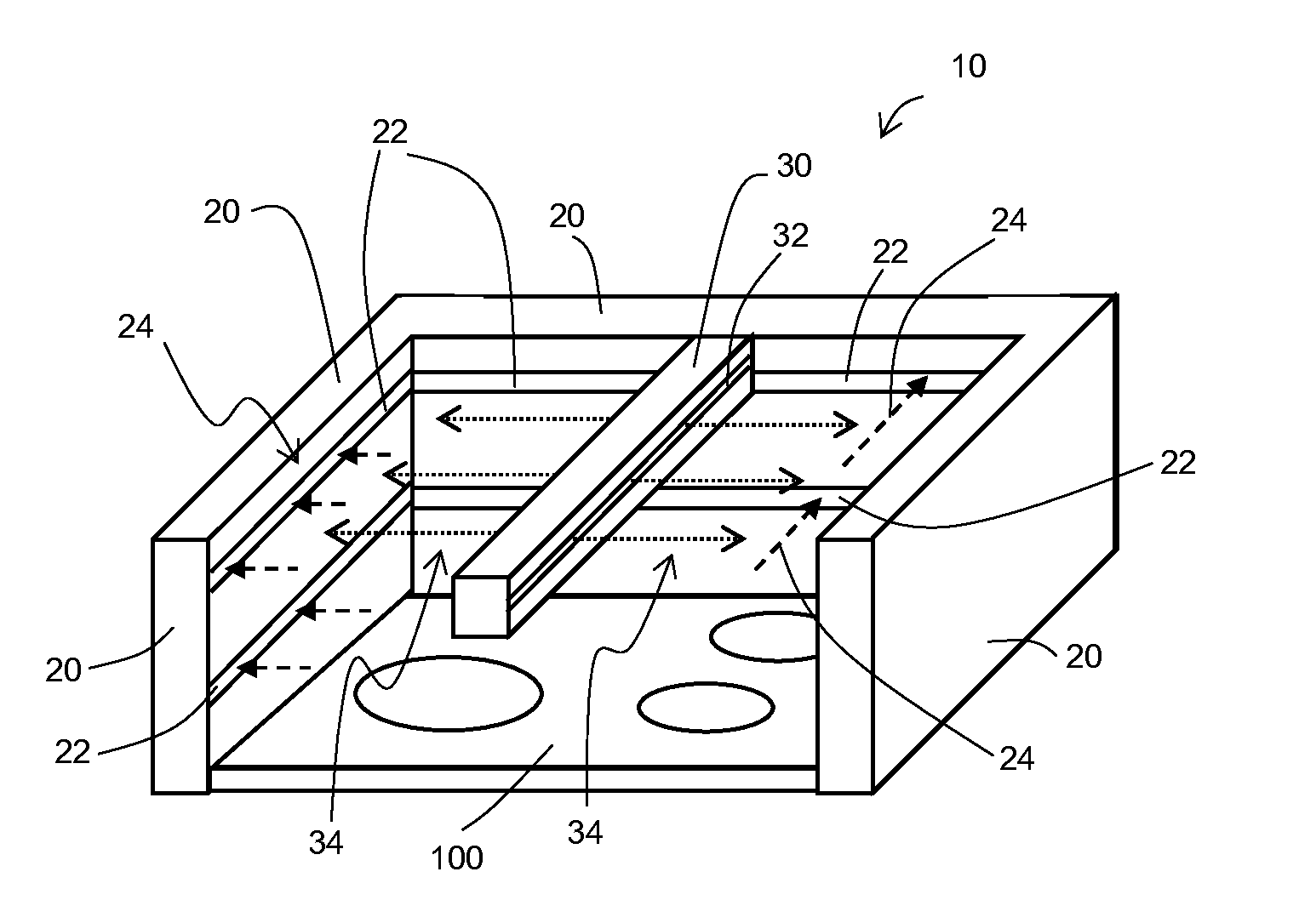
[0028]In a first embodiment as shown in FIG. 1, the suction duct 20 comprises an L-shaped hollow tube preferably having a rectangular cross-section. The suction duct 20 is configured for placement above two adjacent edges 110, 120 of the stovetop 100, a side edge 110 and a back edge 120. Similarly, the supply duct 30 comprises a hollow tube preferably having a rectangular cross-section. The supply duct 30 is configured for placement above an edge 130 of the stovetop 100, such as the side edge 130 opposing the side edge 110 where the suction duct 20 is placed, as shown in FIG. 1. The suction duct 20 and supply duct 30 together form a simple U-shaped structure above and around the stovetop 100, providing a streamlined look while channelling cooking fumes 50 into the air cleaning device 60 to prevent the cooking fumes 50 from pervading the open space where the stovetop 100 is in use. Alternatively, the suction duct 20 may be configured for placement above only one edge 110 of the stove...
second embodiment
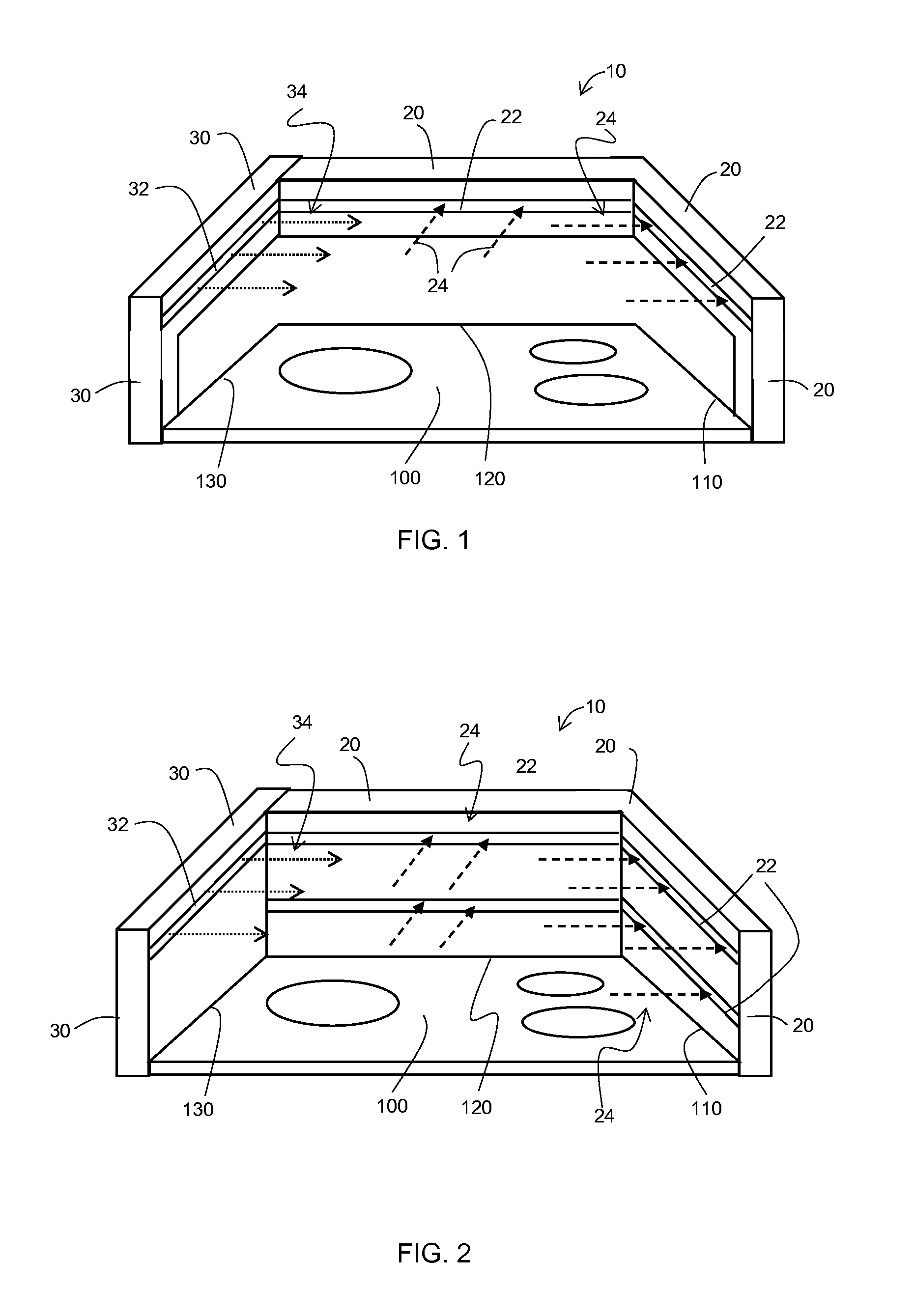
[0029]In a second embodiment as shown in FIG. 2, the suction duct 20 and the supply duct 30 comprise hollow walls extending upwardly from the edges 110, 120130 of the stovetop 100. The supply duct 30 is preferably adjacent the side edge 130 of the stovetop while the suction duct 20 is L-shaped and adjacent the side and back edges 110, 120 of the stovetop 100. Alternatively, the suction duct 20 may be adjacent only the side edge 110 of the stovetop 100. The suction duct 20 preferably comprises a plurality of the inlets 22 in the form of substantially horizontally disposed slots located at different heights on the hollow walls of the suction duct 20, although in other embodiments only one inlet 22 may be provided.
third embodiment
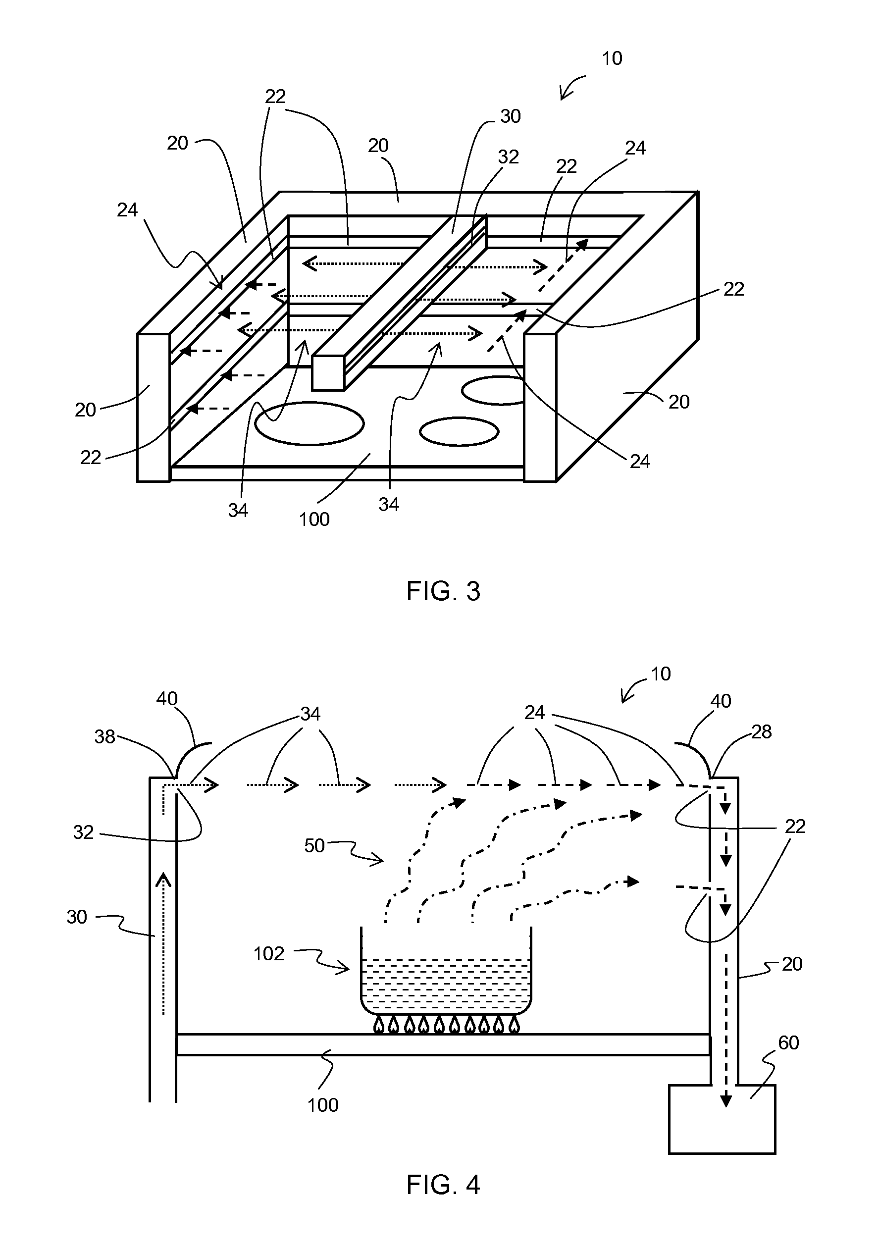
[0030]In a third embodiment as shown in FIG. 3, the supply duct 30 is configured for placement above and extending over the stovetop 100 between two suction ducts 20 provided on either side 110, 130 of the stovetop. The supply duct 30 is preferably placed centrally between the two suction ducts 20 and comprises a hollow tube having a rectangular cross section. The supply duct 30 is provided with at least one outlet 32 on each of two opposing lateral sides of the hollow tube such that each outlet 32 is directed towards each of the suction ducts 20.
[0031]As shown in FIG. 4, the apparatus 10 may comprise an upstanding rim 40 that curves inwardly towards the stovetop 100 provided on a top edge 28 of the supply duct 20 and a top edge 28 of the suction duct 30. The upstanding rim 40 is configured to help guide the air 24 containing the cooking fumes 50 towards the inlet 22 and also enhance the air curtain effect provided by the outflow of air 34.
[0032]Preferably, the apparatus 10 is confi...
PUM
 Abstract
Description
Claims
Application Information
 - Generate Ideas
- Intellectual Property
- Life Sciences
- Materials
- Tech Scout
- Unparalleled Data Quality
- Higher Quality Content
- 60% Fewer Hallucinations
Browse by: Latest US Patents, China's latest patents, Technical Efficacy Thesaurus, Application Domain, Technology Topic, Popular Technical Reports.
© 2025 PatSnap. All rights reserved.Legal|Privacy policy|Modern Slavery Act Transparency Statement|Sitemap|About US| Contact US: help@patsnap.com