Conical concave cap pressure relief valve

Inactive Publication Date: 2007-06-12
DELPHI TECH INC
View PDF11 Cites 4 Cited by
  • Summary
  • Abstract
  • Description
  • Claims
  • Application Information

AI Technical Summary

Benefits of technology

[0004]The present invention provides a pressure relief valve having a valve body with a longitudinal bore opening providing a flow channel extending between first and second ends of the valve body. A valve element is placed in axially movable relationship in the opening of the valve body and is spring biased against a valve seat to create a fluid-tight seal, thereby preventing passage of fuel through the valve when in this closed position. When the fluid force becomes greater than the biasing force of the spring, the valve element is pushed away from the valve seat, thereby creating an opening between the valve element and the valve seat wherethrough fuel may pass.
[0005]The valve element has a substantially conically shaped surface while the valve seat includes a substantially hemispherical surface. When the valve is in its closed position, the conical surface of the valve element sits against the hemispherical surface of the valve sea

Problems solved by technology

Diaphragm-type pressure regulating valves have been used but are large and expensive.
Smaller and less expensive ball-on-seat valves have also been used but are not sufficiently sensitive to changes in the fuel consumption rate of the motor for application as a pressure regulating val

Method used


Image

  • Conical concave cap pressure relief valve
  • Conical concave cap pressure relief valve
  • Conical concave cap pressure relief valve

Examples


Example

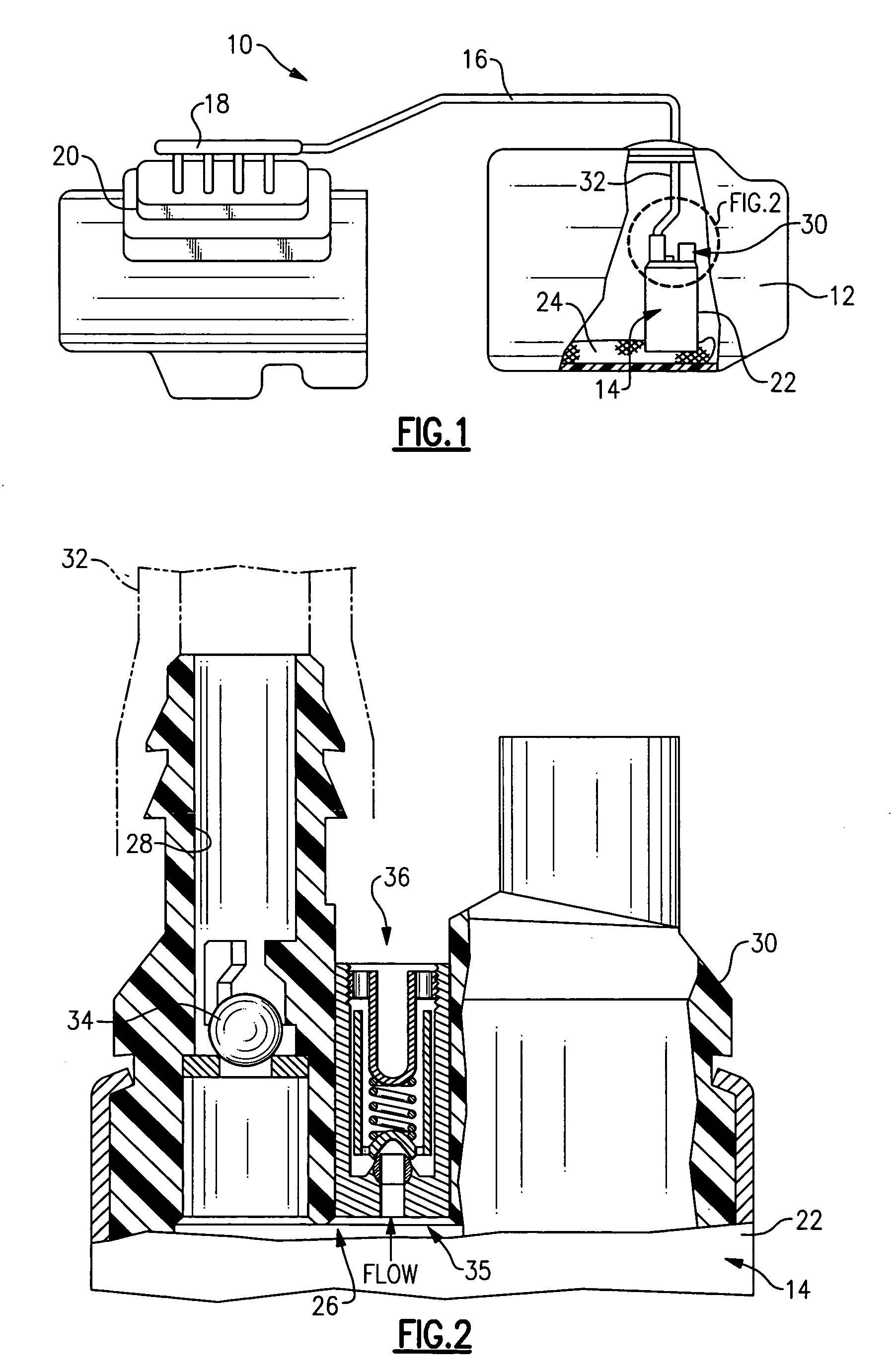
[0013]The present invention provides a pressure relief valve useful in vehicle fuel delivery systems such as fuel delivery system 10 seen in FIG. 1. Vehicle fuel delivery system 10 includes a fuel tank 12 having a high pressure fuel pump 14 connected to a fuel line 16 which leads to a fuel rail 18 connected to individual fuel injectors leading into an engine 20. Fuel pump 14 is operable to deliver fuel under pressure from tank 12 through fuel line 16 to engine 20 as described above.

[0014]Referring also to FIG. 2, a pump housing 22 of the fuel pump 14 surrounds a high pressure pump and an electric motor (not shown) for driving a rotating element of the high pressure pump. The high pressure pump is supplied with fuel from the fuel tank 12 through an inlet screen 24 and discharges fuel into an interior volume 26 of the housing 22 around the electric motor. From the interior volume 26 of the housing 22, the discharge of the high pressure pump flows to the fuel line 16 through a discharg...


PUM


Abstract

A pressure relief valve useful in vehicle fuel delivery systems includes a spring biased, concave conical flow directing surface and a spherical valve seat.

Description

TECHNICAL FIELD[0001]The present invention generally relates to pressure relief valves useful in vehicle fuel delivery systems.BACKGROUND OF THE INVENTION[0002]Various types of pressure relief valves are known for controlling fuel delivery pressure in so-called single-line forward fuel injection systems. Diaphragm-type pressure regulating valves have been used but are large and expensive. Smaller and less expensive ball-on-seat valves have also been used but are not sufficiently sensitive to changes in the fuel consumption rate of the motor for application as a pressure regulating valve in single line forward motor vehicle injection systems.[0003]A prior art pressure regulating valve is seen in U.S. Pat. No. 5,762,101 issued to General Motors Corporation, the entire disclosure of which is incorporated herein by reference. The valve of the '101 patent includes a valve element having a surface which is spring biased to close against a circular valve seat. An annular orifice is created...

Claims


Application Information

Patent Timeline
IPC IPC(8): F02M37/00F02M37/08
CPCF02M37/0029
Inventor PRESTON, GROVER W.
Owner DELPHI TECH INC
Why Eureka
Try Eureka