

Obstacle detection system
- Summary
- Abstract
- Description
- Claims
- Application Information
AI Technical Summary
Benefits of technology
Problems solved by technology
Method used
Image

Examples
embodiments
First Embodiment
[0028]An obstacle detection system according to a first embodiment of the present invention will be described with reference to FIGS. 1-5. The obstacle detection system can be suitably used for a vehicle, for example.
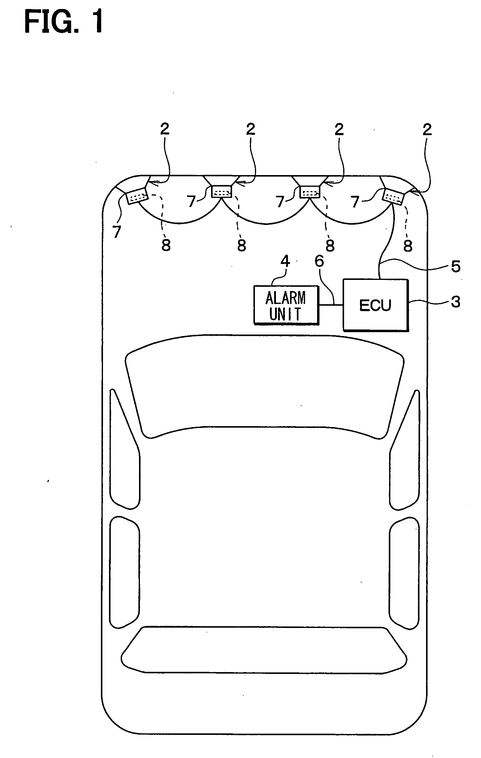
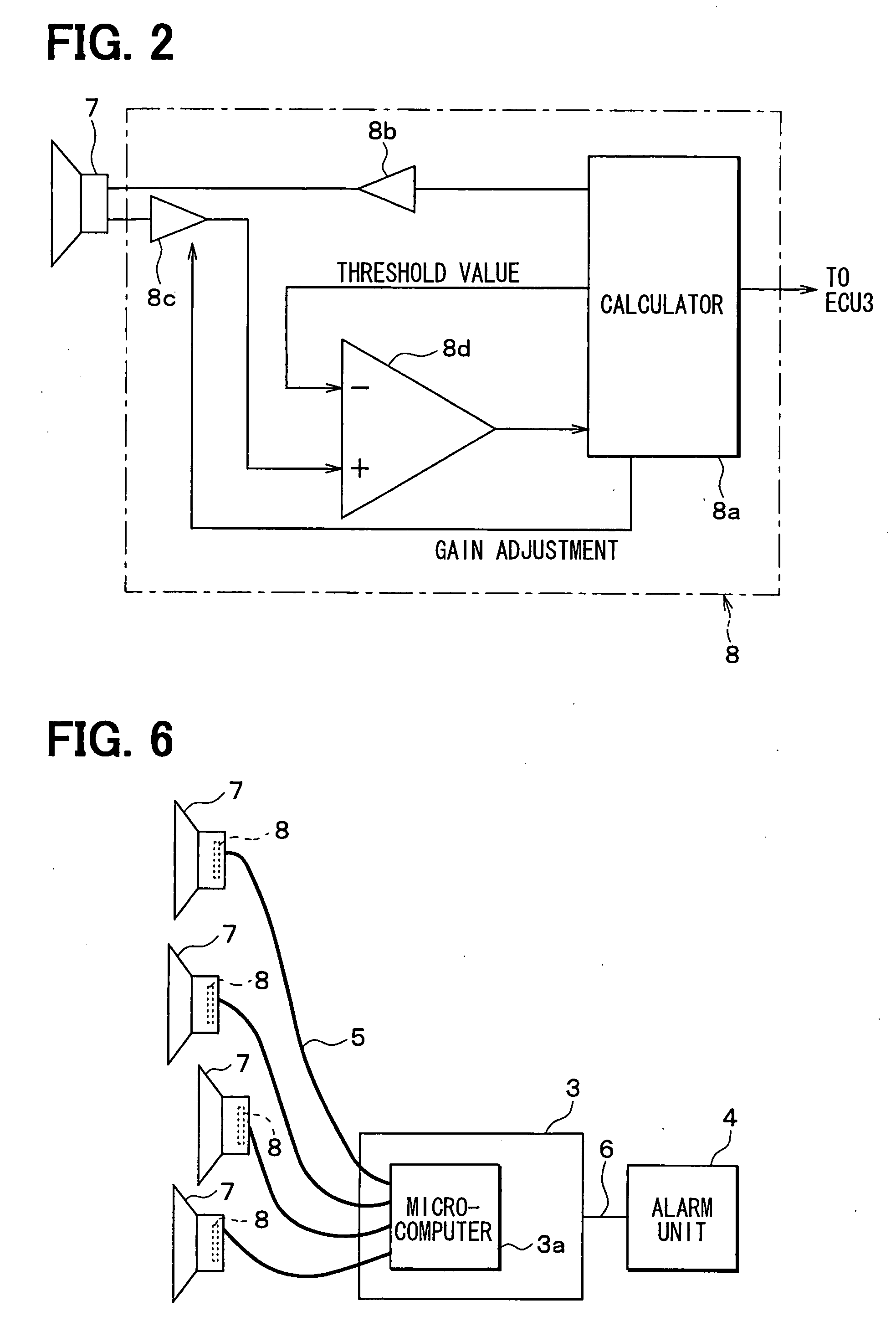
[0029]As shown in FIG. 1, the obstacle detection system which is attached to the vehicle includes multiple ultrasonic sonars 2, a control unit 3 (for example, ECU) and an alarm unit 4. The multiple sonars 2 are respectively communicated with the ECU 3 through a LAN cable 5. The ECU 3 and the alarm unit 4 are connected with each other through a LAN 6, so that an alarm command signal and the like can be transmitted from the ECU 3 to the alarm unit 4.
[0030]The sonar 2 is fixed to a component (such as bumper of vehicle front portion or that of vehicle rear portion) of a chassis of the vehicle, and has a microphone 7 for sending a transmitting wave and receiving a receiving wave. For example, the sonar 2 can be arrayed in the vehicle width direction and arran...
third embodiment
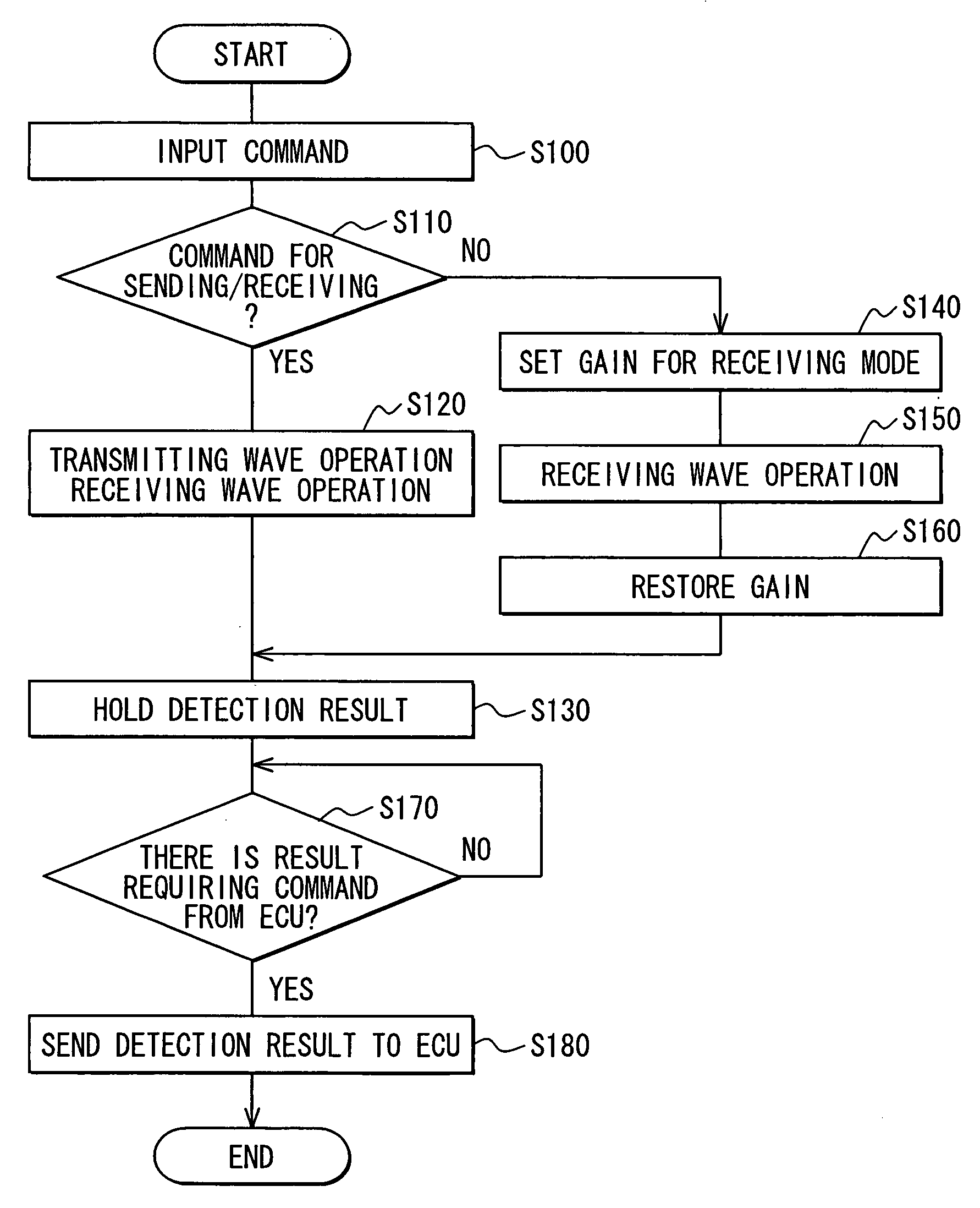
[0075]In the above-described first and second embodiments, the gain when the signal received by the microphone 7 is amplified and the threshold value for determining whether or not the obstacle exits are adjusted. According to a third embodiment of the present invention, additionally, the masking time can be also adjusted.
[0076]As described above, the masking time from the start of the outputting of the transmitting wave until the reverberation disappeared is set. However, it is unnecessary to consider the reverberation for the sonar 2 which is set to have the receiving mode. Therefore, if the masking time is shortened for the sonar 2 which is set to have the receiving mode, the receiving of the receiving wave can be early performed due to the shortening of the masking time. Thus, the obstacle in the range having a shorter distance from the vehicle can be detected.
Other Embodiment
[0077]Although the present invention has been fully described in connection with the preferred embodimen...
PUM
 Abstract
Description
Claims
Application Information