Memory cell comprising one MOS transistor with an isolated body having an improved read sensitivity

Active Publication Date: 2007-02-01
STMICROELECTRONICS CROLLES 2
View PDF11 Cites 19 Cited by
  • Summary
  • Abstract
  • Description
  • Claims
  • Application Information

AI Technical Summary

Benefits of technology

[0016] An object of the present invent

Problems solved by technology

At the end of this state, as illustrated in FIG. 3B, the space charge areas tend to widen, which results in an increase in the transistor threshold voltage.
However, given that there is a dispersion from one cell

Method used


Image

  • Memory cell comprising one MOS transistor with an isolated body having an improved read sensitivity
  • Memory cell comprising one MOS transistor with an isolated body having an improved read sensitivity
  • Memory cell comprising one MOS transistor with an isolated body having an improved read sensitivity

Examples


Example

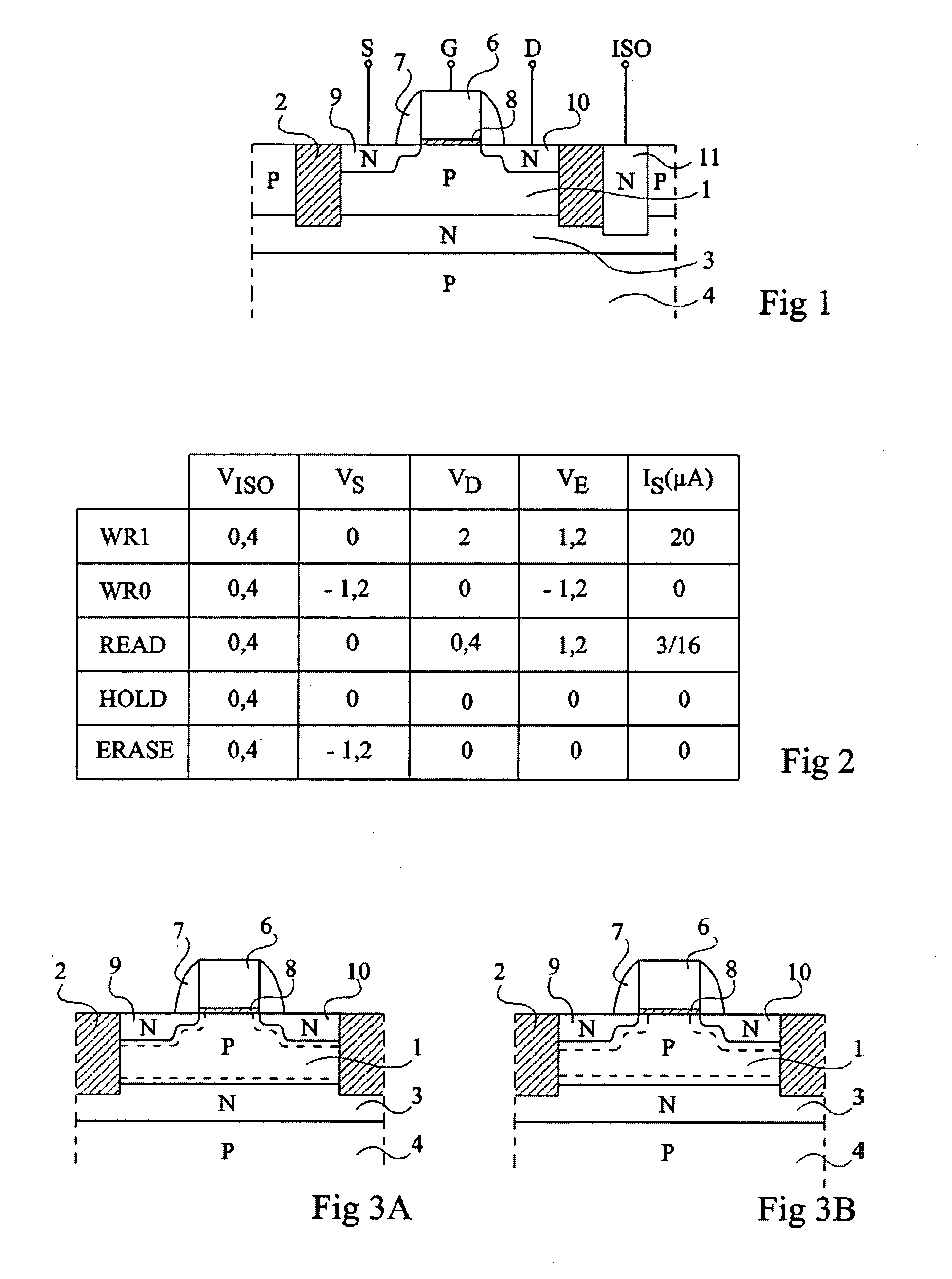
[0030] As usual in the representation of integrated circuits, the various cross-section views are not drawn to scale.

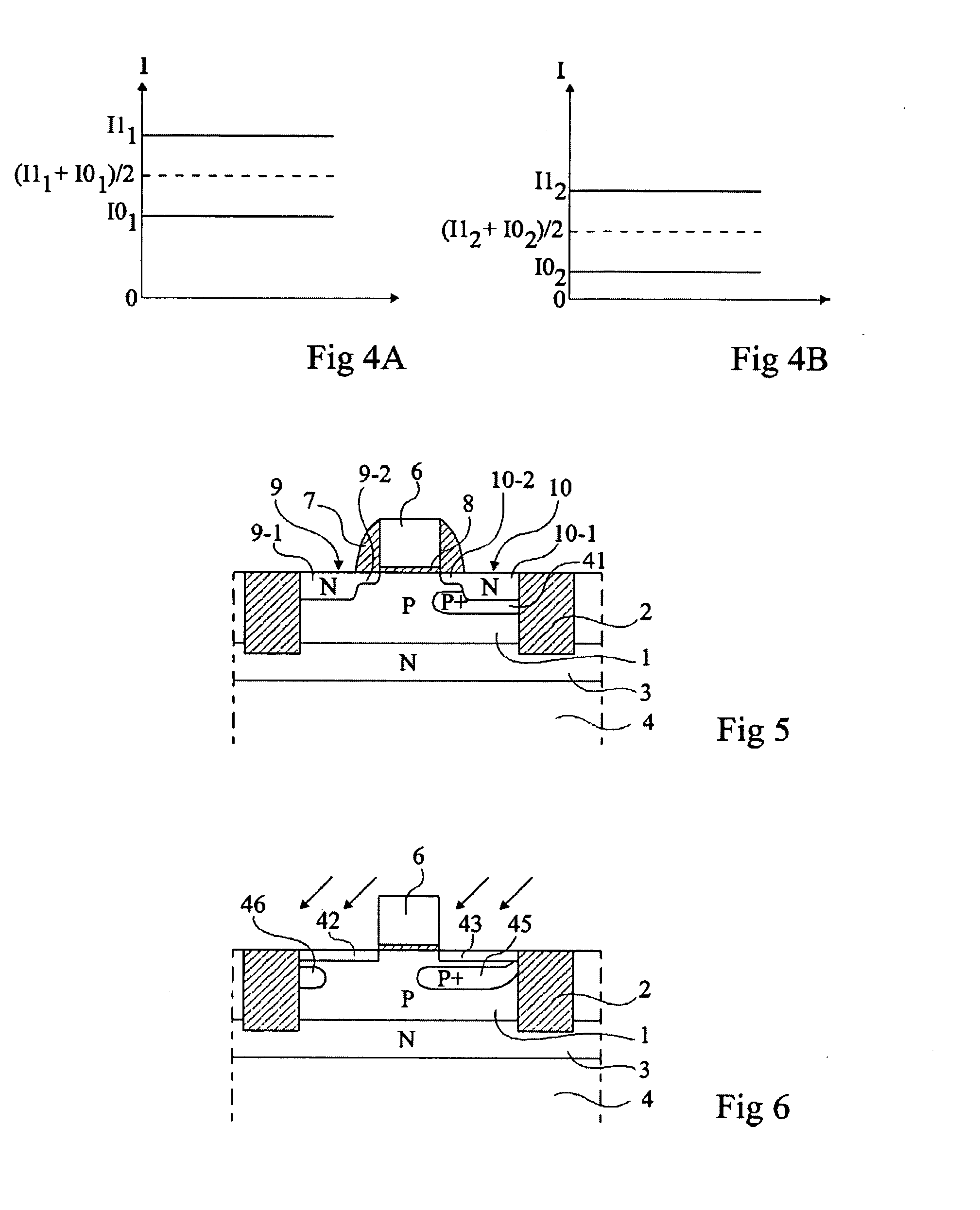
[0031] Statistic studies performed on cell models show that the read error risk (confusion of a 1 and of a 0 or non-detection of a 1 or of a 0) decreases, for a given difference I1−I0, along with the average value of I1+I0, that is, along with the value of Iref. Thus, the risk of a read error is smaller in the case of FIG. 4B than in the case of FIG. 4A.

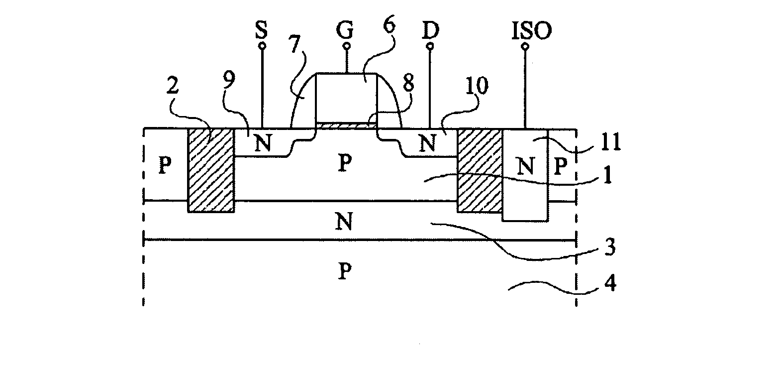
[0032] The inventors have thus formed a memory cell comprising a transistor with a floating body region in which interval I1−I0 is substantially unmodified with respect to a conventional cell such as that shown in FIG. 1 but in which the values of I1 and I0 are smaller.

[0033] The inventors have shown that this result is obtained when the doping of floating body region 1 under the drain region is increased. Thus, the inventors provide, as shown in FIG. 5, forming under drain region 10 a P-type region 41 more heavily-...


PUM


Abstract

A memory cell with one MOS transistor formed in a floating body region isolated on its lower surface by a junction. A region of the same conductivity type as the floating body region but more heavily doped than said region is arranged under the drain region of the MOS transistor.

Description

BACKGROUND OF THE INVENTION [0001] 1. Field of the Invention [0002] The present invention generally relates to DRAM-type memory cells with one transistor formed in a floating body or well delimited depthwise by a junction. [0003] 2. Discussion of the Related Art [0004]FIG. 1 is a simplified cross-section view of an example of such a memory cell. This cell comprises an N-channel MOS transistor formed in a floating body region 1 laterally delimited by an isolating ring 2 and, depthwise, by an N-type layer 3 formed in a P-type substrate 4. The MOS transistor comprises, on either side of a gate region 6 surrounded with spacers 7 and resting on a gate insulator 8, N-type source and drain regions 9 and 10. Each of the source and drain regions comprises a deeper, more heavily doped region outside of the region defined by spacers 7 and a shallower, less heavily doped region under spacers 7. [0005] In the absence of a specific action on the cell, floating body 1 is at a given voltage corresp...

Claims


Application Information

Patent Timeline
IPC IPC(8): H01L29/94G11C16/04
CPCH01L29/7841H01L29/1075
Inventor VILLARET, ALEXANDREMAZOYER, PASCALERANICA, ROSSELLA
Owner STMICROELECTRONICS CROLLES 2
Why Eureka
Try Eureka