System and method for fabricating custom medical implant devices

a technology of medical implants and manufacturing methods, applied in the field of custom medical implant devices, can solve the problems of vascular plaques that are typically non-uniform, block blood vessels, and form bulky occlusions, and achieve the effect of easy dissolution of the cor

Active Publication Date: 2015-11-12
3D SYST INC
View PDF5 Cites 18 Cited by
  • Summary
  • Abstract
  • Description
  • Claims
  • Application Information

AI Technical Summary

Benefits of technology

[0007]The core can be wrapped with a thin filament or film that can harden around the core. In an embodiment, the filament or film material can be heated while it is wrapped around the core. The filament or film material then cools and harden around the core. The contours from the outer surface of the core can formed on the outer surface of the covering. The covering can be hardened and the core can be exposed to a solvent and dissolved away, leaving a custom-made implant device that can be deposited in the patient's cavity. In an embodiment, the hollow and / or porous structure of the core can allow the solvent to more easily dissolve the core.

Problems solved by technology

Such injuries can place a patient in immediate critical condition from obstruction of the airway and in imminent critical condition from oxygen insufficiency in the body.
Similarly, the flow of blood may be compromised by injured and / or blocked blood vessels.
However, vascular plaque is typically non-uniform and often forms in bulky occlusions.
These occlusions place stress on conventional stents via point forces that increase the risk of hinging or denting of the stent.
Denting is caused by an inherent weakness of conventional stents where a vaso-occlusion drives a portion of the stent into the luminary space, thereby substantially enhancing the blockage effect of the vaso-occlusion.
Denting can lead to increased collection of thrombus or flow distortions, which are problematic and can increase stenosis.

Method used


Image

  • System and method for fabricating custom medical implant devices
  • System and method for fabricating custom medical implant devices
  • System and method for fabricating custom medical implant devices

Examples


Embodiment Construction

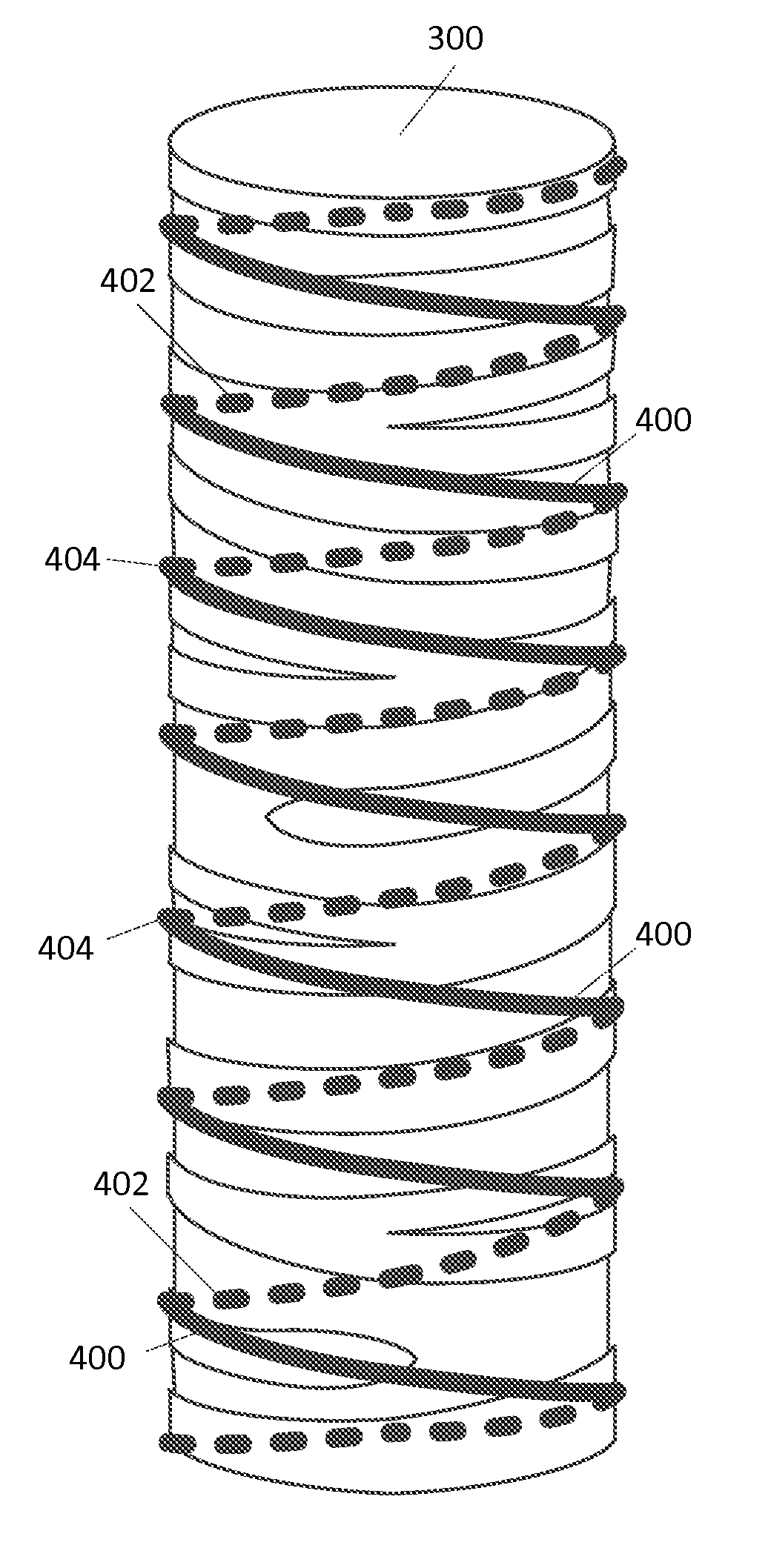
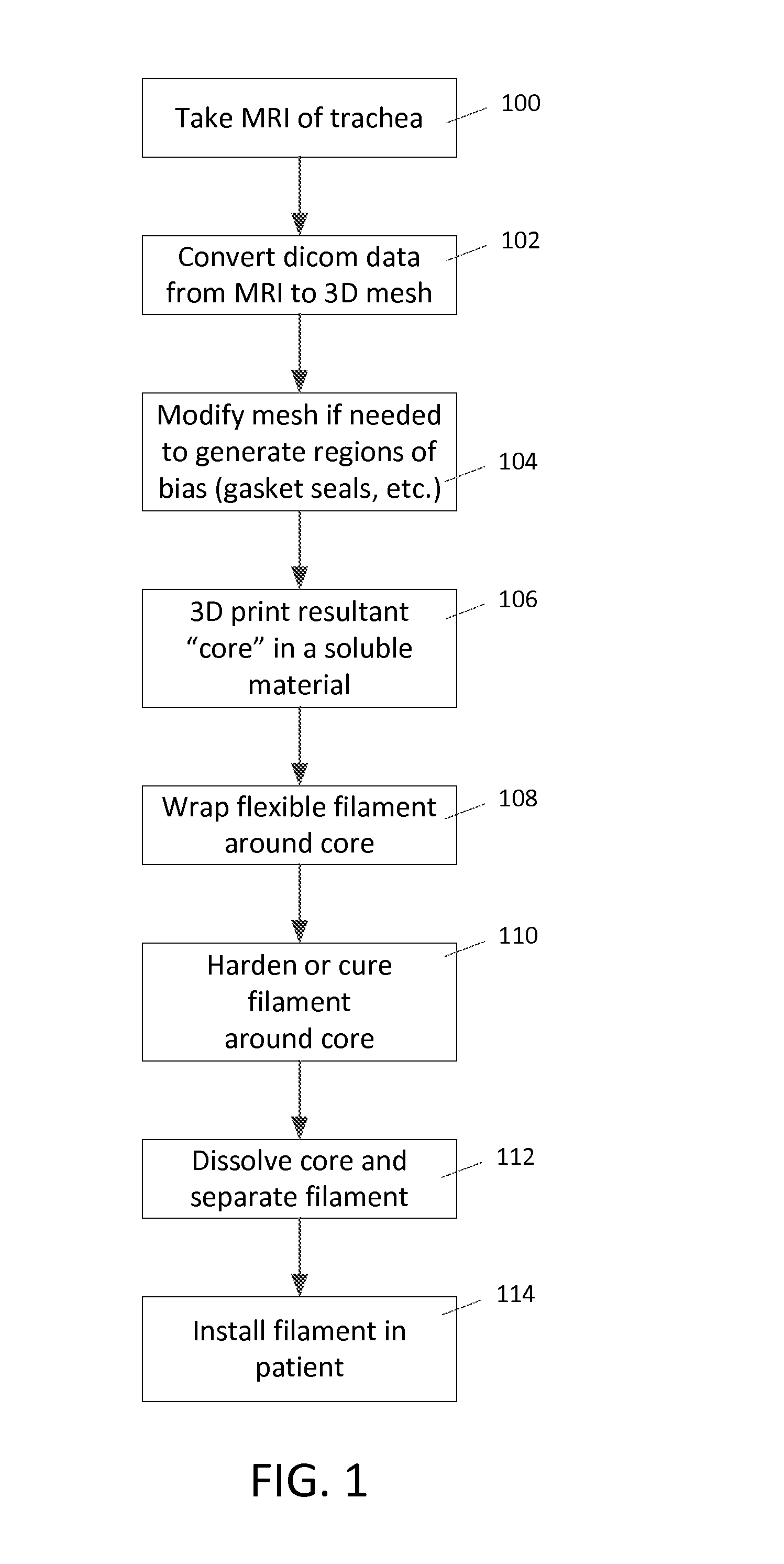
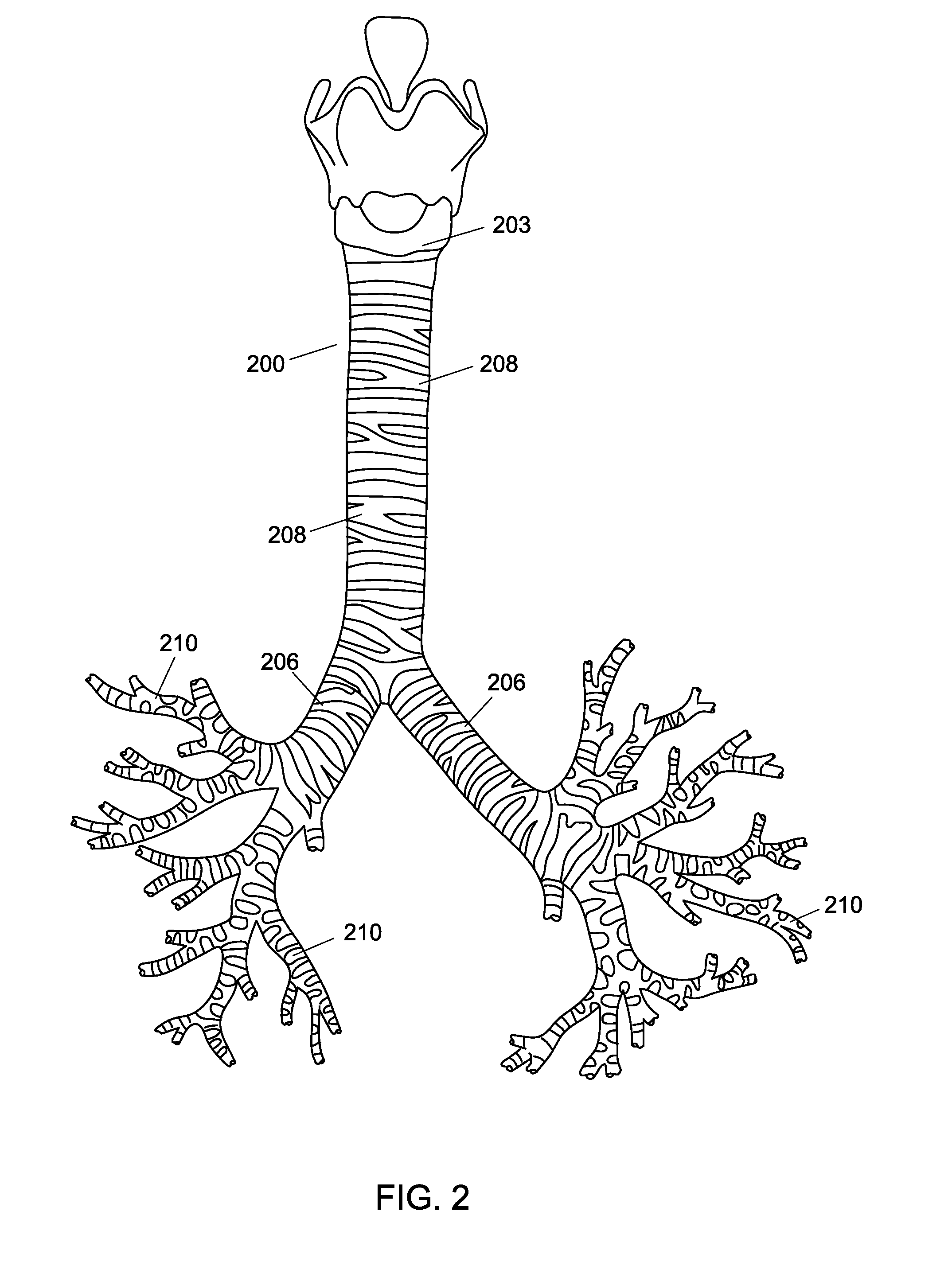
[0015]The present invention is directed towards a method for creating a custom fitting tubular insert for insertion into the inner cavities of a patient. The inner cavities of a patient may include, but are not limited to, the trachea, bronchi, vessels, any part of the airway system, circulatory system, urinary system, and / or digestive system. The method can create a custom-made insert to fit the unique contours of an individual along any portion of a patient's inner cavities. A custom implant that corresponds to the anatomy of the patient can be very desirable because an implant that does not match the patient's anatomy can be uncomfortable and cause injury. For example, cylindrical implants used to keep airway passages open are problematic because they create pressure points that wear down the patient's trachea. Thus, a custom fitting structure would greatly improve the successful use of medical implants within patients.

[0016]In an embodiment, the method for creating a custom tubu...


PUM

PropertyMeasurementUnit
softening temperaturesaaaaaaaaaa
surface measurementsaaaaaaaaaa
solubleaaaaaaaaaa

Abstract

A method for creating tubular inserts is useful for creating custom fitted inserts that correspond to the anatomy of a patient and solve the problem of pressure points, wear of the implant, damage to surrounding tissue, and denting. Surface measurements of the affected portion of a patient's internal cavity are obtained. Those measurements are used to design a core. The core is 3D printed with a soluble material. The core is wrapped with a thin filament or film such that the contours from the core develop on the outer surface of the covering. The covering is hardened and the core is dissolved away, leaving a custom-made implant device that can be deposited in the patient's cavity.

Description

CROSS REFERENCE TO RELATED APPLICATIONS[0001]This application claims priority to U.S. Provisional Patent Application No. 61 / 991,714, “System And Method For Fabricating Custom Medical Implant Devices” filed May 12, 2014 which is hereby incorporated by reference in its entirety.BACKGROUND[0002]The flow of air and blood within the body are vital, life-sustaining functions and in some situations, implanted medical devices can be used to maintain the proper flow of air and / or blood within a patient after an injury. For example, the flow of air may be compromised by injuries to the trachea and bronchi (tracheobronchial injuries, or “TBIs”). Such injuries can place a patient in immediate critical condition from obstruction of the airway and in imminent critical condition from oxygen insufficiency in the body. TBIs are a common medical condition, occurring most frequently from blunt or penetrating trauma to the neck or chest, inhalation of harmful fumes or smoke, or aspiration of liquids or...

Claims


Application Information

Patent Timeline
Patent Type & Authority Applications(United States)
IPC IPC(8): A61M16/04A61F2/92B29C53/82B29C67/00B29C53/60B29C53/58
CPCA61M16/0434B29C53/60B29C53/584B29C53/822B29C67/0055A61M2205/02B29K2067/046B29K2911/00B29L2031/7546B33Y10/00B33Y80/00A61F2/92A61M2207/00A61M16/0406A61F2210/0076A61F2210/0071A61F2/88A61F2/885A61F2240/002A61F2002/046B29C33/52B29L2031/753B29C41/14A61B5/055A61B5/1075A61B5/1076A61B5/1077G01R33/5608A61B6/032A61B6/50A61B6/504B29L2031/7532B29C53/587B29C53/66B29C64/106A61F2/82A61F2/30942A61F2002/30948A61F2002/30957
Inventor DUNNE, PATRICK C.
Owner 3D SYST INC
Why Eureka
Try Eureka