
Device and method for controlling the position of a head relative to a tape within a tape transport system

a technology of a transport system and a head is applied in the field of devices and methods for controlling the position of the head relative to the tape within the transport system, which can solve the problems of increased inter-symbol interference, reduced distance between adjacent bit cells, and inability to maintain the alignment of the head carrier,

Active Publication Date: 2015-11-12
INT BUSINESS MASCH CORP
View PDF2 Cites 3 Cited by
  • Summary
  • Abstract
  • Description
  • Claims
  • Application Information

AI Technical Summary

Benefits of technology

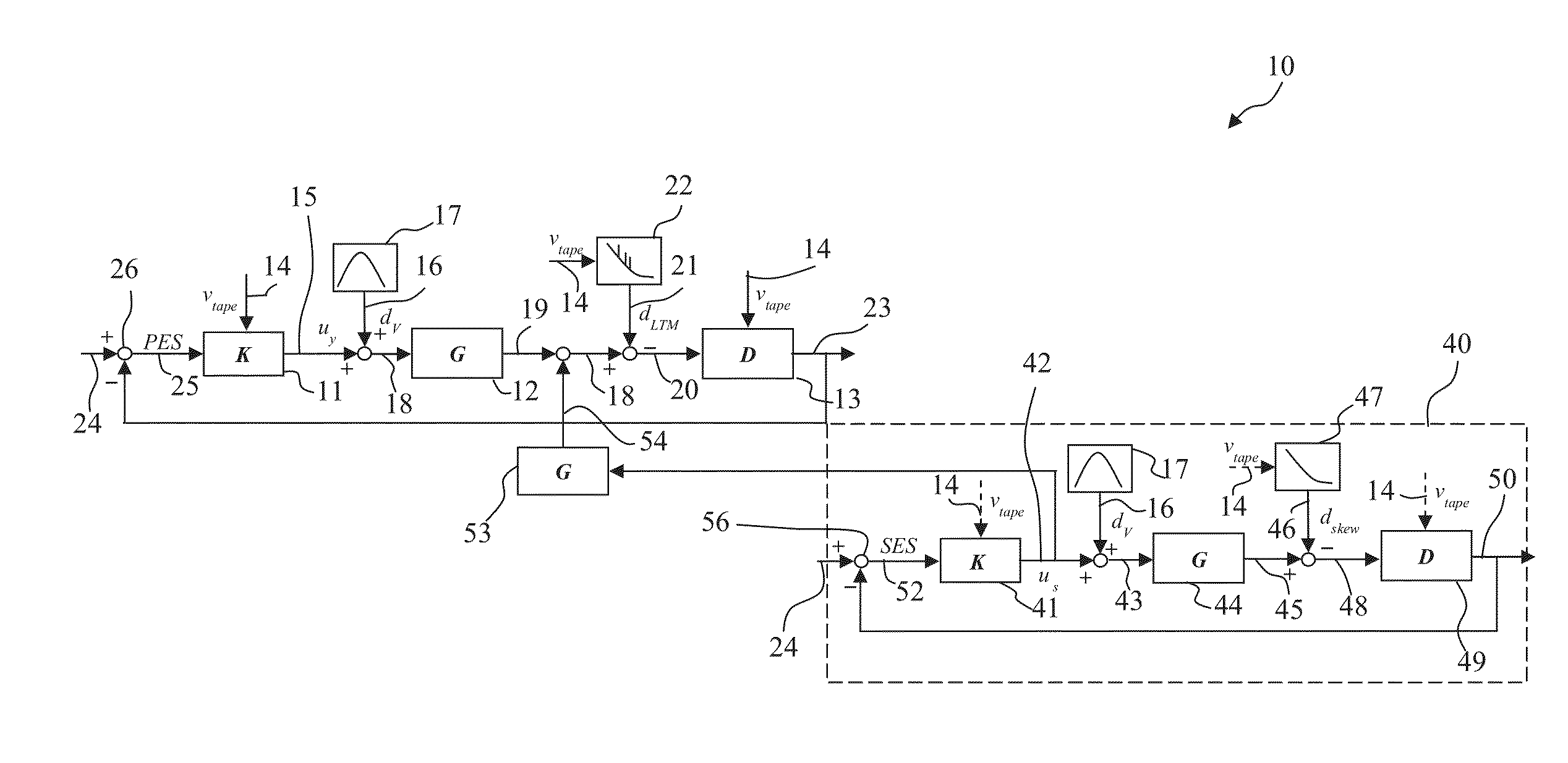
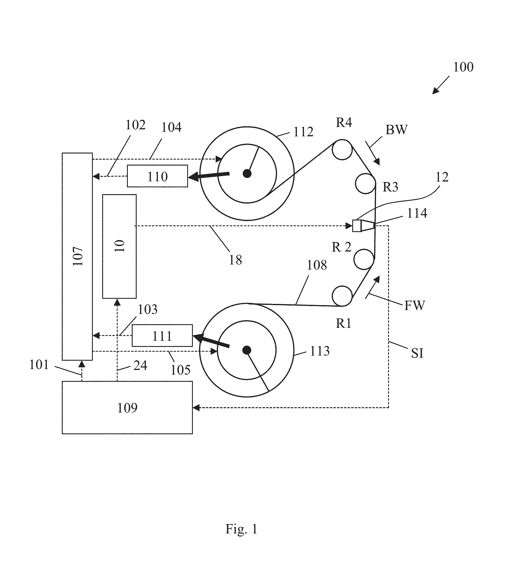
The present invention provides a track-follow control system for controlling the position of a head relative to a tape within a tape transport system. The system includes a controller device that generates a control signal as a function of a position error signal, which indicates a difference between the actual position of the head and a target position. An actuator changes the actual position of the head based on the control signal. The system also includes a feedback mechanism that adjusts the control signal based on a difference between the actuator output signal and a lateral tape motion signal, which indicates a lateral motion of the tape. The system can select from multiple controller device configurations based on the vibration frequency domain profile of the head and the tape. The technical effect of the invention is to improve the accuracy and stability of the track-follow control system, which ensures the head stays in the correct position relative to the tape for efficient data reading and writing.

Problems solved by technology

However, an increase in linear densities can lead to a decrease of the distance between adjacent bit cells, which in turn can lead to an increase of inter-symbol interferences.
Furthermore, operation of tape drive systems requires robust performance of the track-follow control system under shock and vibration conditions.
Increasing the tape track density tightens further the tolerance in the acceptable track following error, making it increasingly more challenging to meet the performance specifications under vibration conditions.
Operation at different tape speeds creates conflicting requirements in the track-follow control system.
With this approach though, there is a trade-off between the performance improvements by compensating the disturbance and the delay effects at low tape speeds.

Method used


Image

  • Device and method for controlling the position of a head relative to a tape within a tape transport system
  • Device and method for controlling the position of a head relative to a tape within a tape transport system
  • Device and method for controlling the position of a head relative to a tape within a tape transport system

Examples


Embodiment Construction

[0029]According to an embodiment of a first aspect of the present invention, a track-follow control system for controlling the position of a head relative to a tape within a tape transport system is provided. The track-follow control system includes a controller device for generating a control signal as a function of a position error signal, wherein the position error signal indicates a difference between the actual position of the head and a target position of the head relative to the tape, and an actuator for changing the actual position of the head dependent on the control signal. The track-follow control system is adapted to select a configuration for the controller device from a plurality of configurations dependent on an operating tape speed, wherein the plurality of controller device configurations are pre-determined (i.e., in advance) depending on a vibration frequency domain profile indicative of environmental vibrations induced to the head and the tape to determine the con...


PUM

PropertyMeasurementUnit
track densitiesaaaaaaaaaa
linear densitiesaaaaaaaaaa
distanceaaaaaaaaaa

Abstract

Controlling the position of a head within a tape transport system. A track-follow control system (TFCS) includes a controller device for generating a control signal as a function of a position error signal (PES), wherein the PES indicates a difference between the actual and target positions of the head relative to the tape, and an actuator for changing the actual position. The TFCS is adapted to select a controller device configuration from a plurality of configurations dependent on an operating tape speed. The configurations are predetermined depending on a vibration frequency domain profile indicative of environmental vibrations induced to the head and tape to determine the control signal for adjusting an actuator output signal relative to a lateral tape motion signal. The TFCS is also adapted to feed-back a signal depending on a difference of the actuator output signal and the lateral tape motion signal to generate the PES.

Description

CROSS-REFERENCE TO RELATED APPLICATION[0001]This application is a Continuation application of co-pending U.S. patent application Ser. No. 14 / 315,427 filed on Jun. 26, 2014, which claims priority under 35 U.S.C. §119 from United Kingdom Patent Application No. 1311965.6 filed Jul. 4, 2013, both of which are incorporated herein by reference in their entirety.BACKGROUND OF THE INVENTION[0002]The present invention relates generally to tape storage systems. More specifically, the present invention relates to a device and method for controlling the position of a head relative to a tape within a tape transport system, considering lateral tape motion and environmental vibrations.[0003]In modern tape storage systems, the capacity and performance of the tape storage systems have increased considerably. However, to achieve higher cartridge or tape capacities and improved performance, further advances in several areas are necessary. Increases in linear and track densities on the tape can be requ...

Claims


Application Information

Patent Timeline
Patent Type & Authority Applications(United States)
IPC IPC(8): G11B5/584G11B5/56
CPCG11B5/56G11B5/584G11B15/602
Inventor ARGUMEDO, ARMANDO J.BUI, NHAN X.HARPER, DAVID H.INCH, RANDY C.JUDD, KEVIN B.LANTZ, MARK A.PANTAZI, ANGELIKLTAKETOMI, TOMOKO
Owner INT BUSINESS MASCH CORP
Learn More