Transcatheter valve with paravalvular leak sealing ring

a transcatheter valve and paravalvular technology, applied in the field of heart valve replacement, can solve the problems of paravalvular leakage, pv leakage, and inability to fully seal the valve,

Active Publication Date: 2015-11-19
ST JUDE MEDICAL CARDILOGY DIV INC
View PDF19 Cites 103 Cited by
  • Summary
  • Abstract
  • Description
  • Claims
  • Application Information

AI Technical Summary

Problems solved by technology

After implantation, imperfect sealing between the cuff and the site of implant may cause complications such as paravalvular leakage (“PV leak”), or blood flowing through a channel between the structure of the implanted valve and cardiac tissue as a result of the imperfect sealing.

Method used


Image

  • Transcatheter valve with paravalvular leak sealing ring
  • Transcatheter valve with paravalvular leak sealing ring
  • Transcatheter valve with paravalvular leak sealing ring

Examples


Embodiment Construction

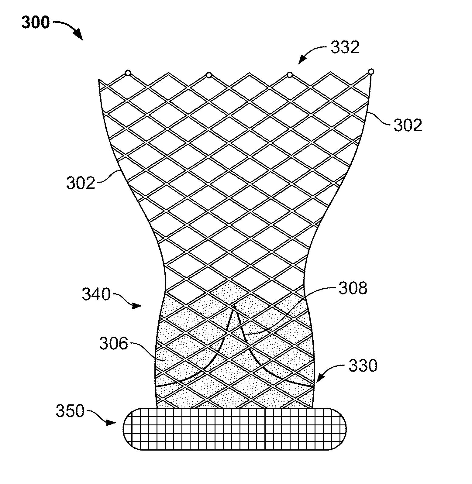
[0027]As used herein, the term “inflow end,” when used in connection with a prosthetic heart valve, refers to the end of the heart valve through which blood enters when the valve is functioning as intended. The term “outflow end,” when used in connection with a prosthetic heart valve, refers to the end of the heart valve through which blood exits when the valve is functioning as intended. As used herein, the terms “generally,”“substantially,” and “about” are intended to mean that slight deviations from absolute are included within the scope of the term so modified. Like numbers refer to similar or identical elements throughout. When used herein in the context of a prosthetic heart valve, or a component thereof, the lengthwise or axial direction refers to a direction along a longitudinal axis passing through the center of the stent or heart valve. When used herein in the context of a prosthetic heart valve, or a component thereof, the circumferential direction refers to a direction e...


PUM


Abstract

A prosthetic heart valve includes a collapsible and expandable stent extending from an inflow end to an outflow end and a plurality of prosthetic valve leaflets coupled to the stent. The prosthetic heart valve may also include a sealing ring coupled to the inflow end of the stent, the sealing ring comprising a tube extending circumferentially around the inflow end of the stent. The tube may be formed from a wire coiled into a repeating shape, such as a rectangle or a diamond, so that the tube is collapsible. A covering may at least partially surround the tube. The sealing ring may include a first filler positioned within the tube and / or a second filler positioned between the tube and the covering.

Description

CROSS-REFERENCE TO RELATED APPLICATIONS[0001]The present application claims the benefit of the filing date of U.S. Provisional Patent Application No. 61 / 994,253, filed May 16, 2014, the disclosure of which is hereby incorporated by reference herein.BACKGROUND[0002]The present disclosure relates to heart valve replacement and, in particular, to collapsible prosthetic heart valves. More particularly, the present disclosure relates to collapsible prosthetic transcatheter heart valves which minimize or reduce paravalvular leaks.[0003]Prosthetic heart valves that are collapsible to a relatively small circumferential size can be delivered into a patient less invasively than valves that are not collapsible. For example, a collapsible valve may be delivered into a patient via a tube-like delivery apparatus such as a catheter, a trocar, a laparoscopic instrument, or the like. This collapsibility can avoid the need for a more invasive procedure such as full open-chest, open-heart surgery.[000...

Claims


Application Information

Patent Timeline
Patent Type & Authority Applications(United States)
IPC IPC(8): A61F2/24
CPCA61F2/2418A61F2220/0075A61F2210/0061A61F2/2412A61F2230/001A61F2230/0034A61F2230/0078A61F2250/0069A61F2210/0014A61F2230/0017A61F2230/0019A61F2/2436A61F2/2472
Inventor MORIN, KRISTEN T.PARA, ANDREA N.BRAIDO, PETER N.KHOUENGBOUA, OTTBENSON, THOMAS M.KUMAR, SARAVANA B.MOSEMAN, BRUCESATAM, GAURAV
Owner ST JUDE MEDICAL CARDILOGY DIV INC
Why Eureka
Try Eureka