
Double-side thick film network on ceramic card

a technology of thick film network card and ceramic card, which is applied in the direction of coupling device connection, machine/engine, instruments, etc., can solve the problems of connectors being temporarily lost contact with the pads, connectors being subject to being disconnected, and little support for maintaining the proper position of connectors

Active Publication Date: 2015-11-26
VITESCO TECH USA LLC
View PDF4 Cites 5 Cited by
  • Summary
  • Abstract
  • Description
  • Claims
  • Application Information

AI Technical Summary

Benefits of technology

The present invention is a ceramic card that has a thick film network with conductive vias formed as part of the card. This allows the pads and pad senders to be formed on both sides of the card. This configuration maintains contact when one of the connectors is subjected to bending force or is otherwise displaced, maintaining contact with at least one of the pads, and allowing the system to still function. The double sided thick film network allows for each connector to touch both sides of one of the pads, and still maintain electrical communication with the level sender, thus eliminating the failure mode of intermittent contact with the thick film network card resulting from movement of the connector. Each connector also includes a first protrusion and a second protrusion that create inflection points on the card, allowing the card to be placed between the inflection points, placing the connector in electrical communication with the pad. The connection between each connector and a corresponding pad is substantially similar.

Problems solved by technology

The connection between a connector and a pad on the network card is subject to becoming disconnected due to the connector moving out of position, and losing contact with one of the pads.
There is very little support for maintaining the proper location of the connector relative to the corresponding pad.
When the connector is exposed to various bending forces, the connector may temporarily lose contact with the pad, or become disconnected from the pad completely.

Method used


Image

  • Double-side thick film network on ceramic card
  • Double-side thick film network on ceramic card
  • Double-side thick film network on ceramic card

Examples


Embodiment Construction

[0035]The following description of the preferred embodiment(s) is merely exemplary in nature and is in no way intended to limit the invention, its application, or uses.

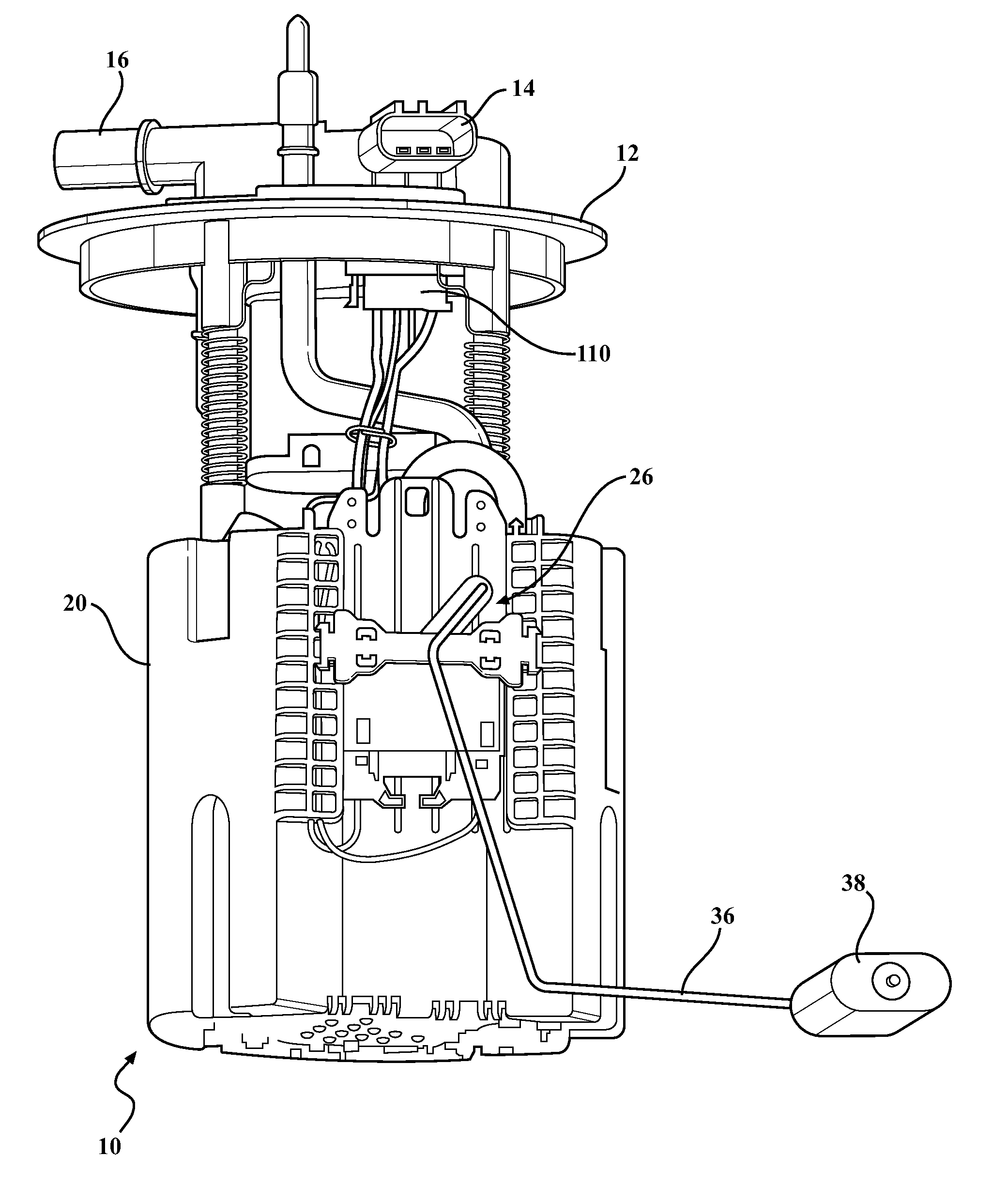
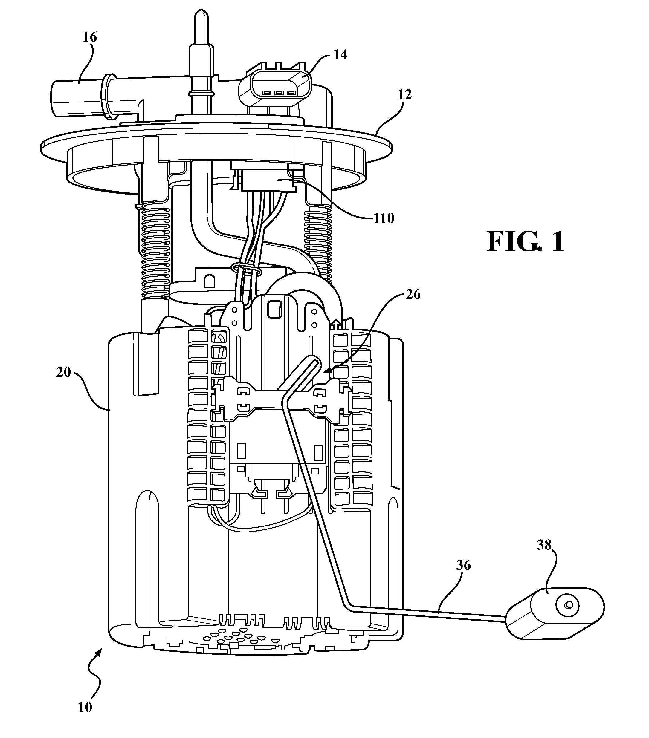
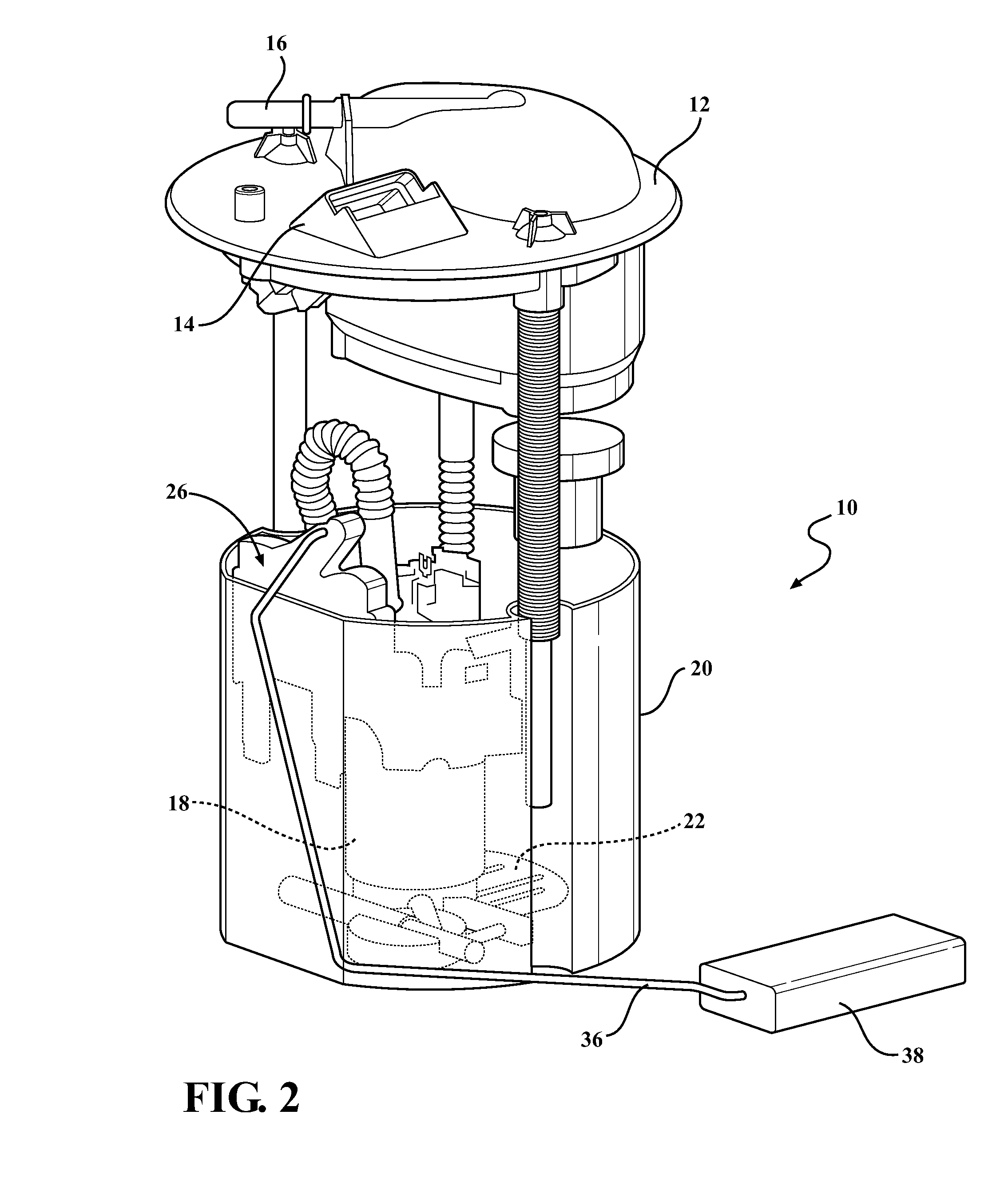
[0036]A fuel module having a thick film network (TFN) sensor card is shown in the Figures generally at 10. Referring to the Figures generally, the fuel module 10 includes a flange 12, where the flange 12 has a connector 14 integrally formed as part of the flange 12, and a port 16 which is also formed as part of the flange 12. The fuel module 10 also includes a fuel pump 18 located in a reservoir 20, along with a filter 22, and various connectors and hoses. The fuel pump 10 functions to transfer fuel from the reservoir 20 through the various connectors and hoses, and out of the port 16.

[0037]Also partially disposed in the reservoir 20 is a holder assembly 24, which is connected to a sidewall of the reservoir 20. The holder assembly 24 supports a sensor assembly, shown generally at 26. The sensor assembly 26 includes a ...


PUM


Abstract

A ceramic card having a thick film network, with conductive vias formed as part of the card. Each of the vias is in electrical communication with both sides of the thick film network, allowing the pads and the pad senders to be formed on both sides of the card. This configuration maintains the contact when one of the connectors is subjected to bending force or is otherwise displaced, maintaining contact with at least one of the pads, and allowing the system to still function. The double sided thick film network allows for each connector to touch both sides of one of the pads, and still maintain electrical communication with the level sender, thus eliminating the failure mode of intermittent contact with the thick film network resulting from movement of the connector.

Description

CROSS-REFERENCE TO RELATED APPLICATIONS[0001]This application claims the benefit of U.S. Provisional Application No. 62 / 001,996 filed May 22, 2014. The disclosure of the above application is incorporated herein by reference.FIELD OF THE INVENTION[0002]The invention relates generally to a connector for a double-sided thick film network card for a level sender in a fuel module.BACKGROUND OF THE INVENTION[0003]Level senders in fuel modules are generally known, and are disposed in gas tanks of vehicles for detecting the level of fuel in the fuel tank. Typical fuel modules have a level sender with some type of circuit disposed on a network card. There is also a float connected to a lever assembly, and the lever assembly is connected to some type of bracket that is in contact with the network card. As the float changes position within the gas tank as the fuel level changes, the bracket changes position relative to the card, and therefore changes the configuration of the circuit, producing...

Claims


Application Information

Patent Timeline
IPC IPC(8): G01F23/36H01H21/22H01R12/72
CPCG01F23/363H01R12/72H01H2231/038H01H2221/016H01H21/22
Inventor BRIGGS, PAUL F.WATTAI, JOHN PATRICKKADLER, MATTHIASPETER, ROBERT
Owner VITESCO TECH USA LLC
Learn More