Connector

a technology of connectors and terminals, applied in the direction of coupling contact members, coupling device connections, two-part coupling devices, etc., can solve the problems of large frictional resistance between the terminals, coarse surface roughness of fractured surfaces, and low frictional resistance between the mating terminals when inserting and releasing the connectors. , the degree of freedom of design of the terminal shape can be relatively high, the effect of improving the operation feel of the insertion and release of the connector

Active Publication Date: 2015-11-26
IRISO ELECTRONICS CO LTD
View PDF4 Cites 12 Cited by
  • Summary
  • Abstract
  • Description
  • Claims
  • Application Information

AI Technical Summary

Benefits of technology

[0033]In order to achieve connector coupling that is provided with the floating structure that movably supports the movable housing with respect to the fixed housing when the connector is fitted to the mating connector, even if there is positional displacement between one connector and the other connector and even if fitted obliquely, the fitting of both connectors can be performed reliably. Furthermore, the permissible range of displacement in the width direction and the permissible range of displacement in angle while fitting the two connectors together can be increased.
[0034]According to the connector of the present disclosure, contact with the mating terminal can be reliably made with the front terminal and the rear terminal. Since contact with the mating terminal is made through a flat plate surface of the terminal, frictional resistance between the mating terminal when inserting and releasing the connector is low and operation feel during insertion and release of the connector can be improved. Furthermore, degree of freedom of design of the terminal shape can be relatively high.
[0035]Furthermore, according to the connector of the present disclosure, even if an irregular fitting, including positional displacement of the connector with respect to the mating connector and occurrence of an oblique connection, is performed, the contact reliability between the terminals is high.

Problems solved by technology

However, the terminals used in the above connector are terminals that are each formed by press punching a flat plate of a terminal material, and the fractured surfaces created by the pressing are used as contacts; accordingly, the surface roughness of the fractured surfaces are coarse and the frictional resistance between the terminals when one of the connectors are mounted to or dismounted from (when inserted into or released from) the other connector tends to be large.
Accordingly, the operation feel when inserting and releasing the connector may disadvantageously be bad.
Furthermore, since the bending direction of the contact is the plate surface direction of the terminal, when coming in contact with the mating terminal, the contact pressure tends to become high, and in order to keep the contact pressure within a desired numerical range, the degree of freedom of designing the shape of the terminal is, disadvantageously, relatively small.

Method used


Image

  • Connector
  • Connector
  • Connector

Examples


first exemplary embodiment

FIGS. 1, and 3 to 9

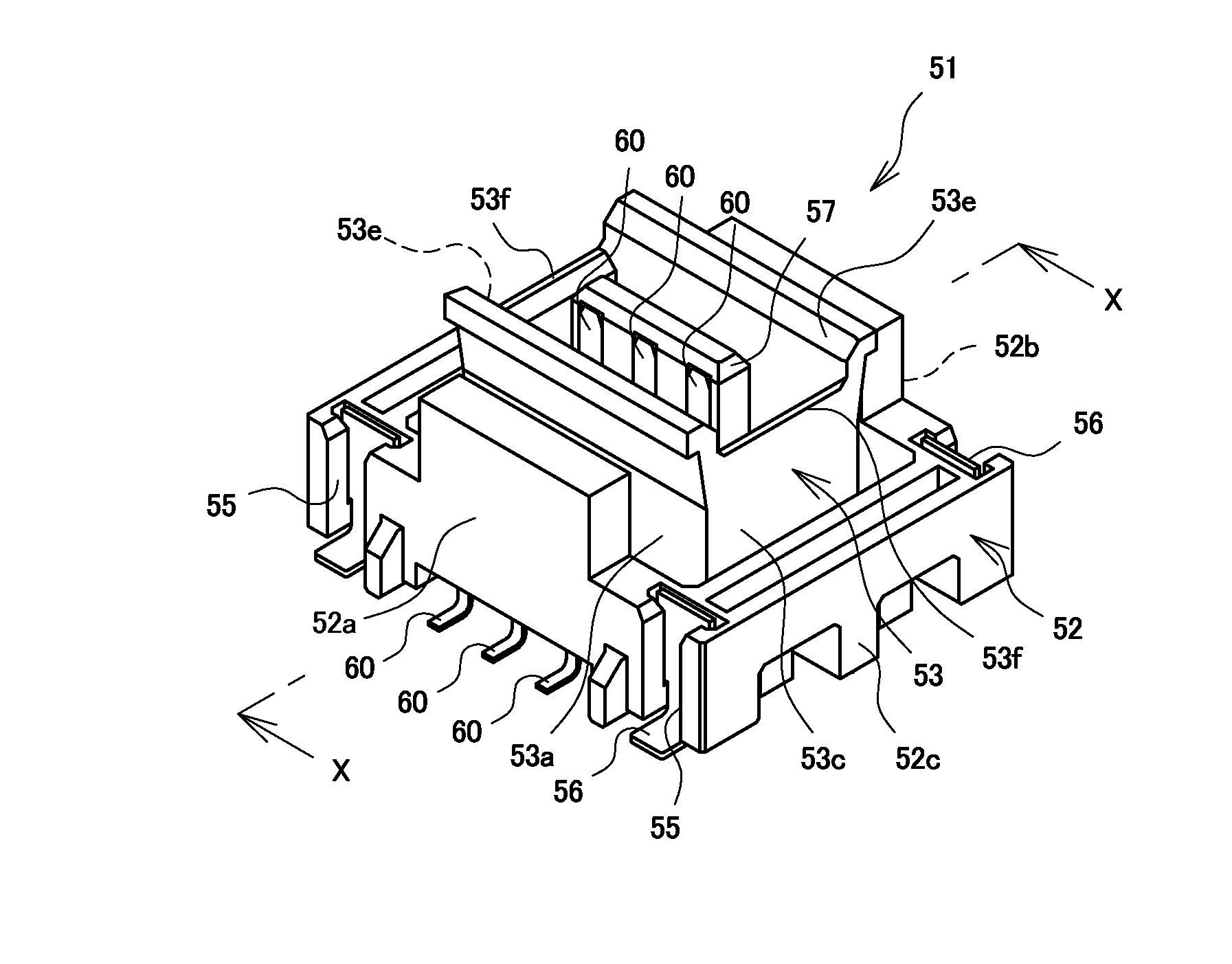
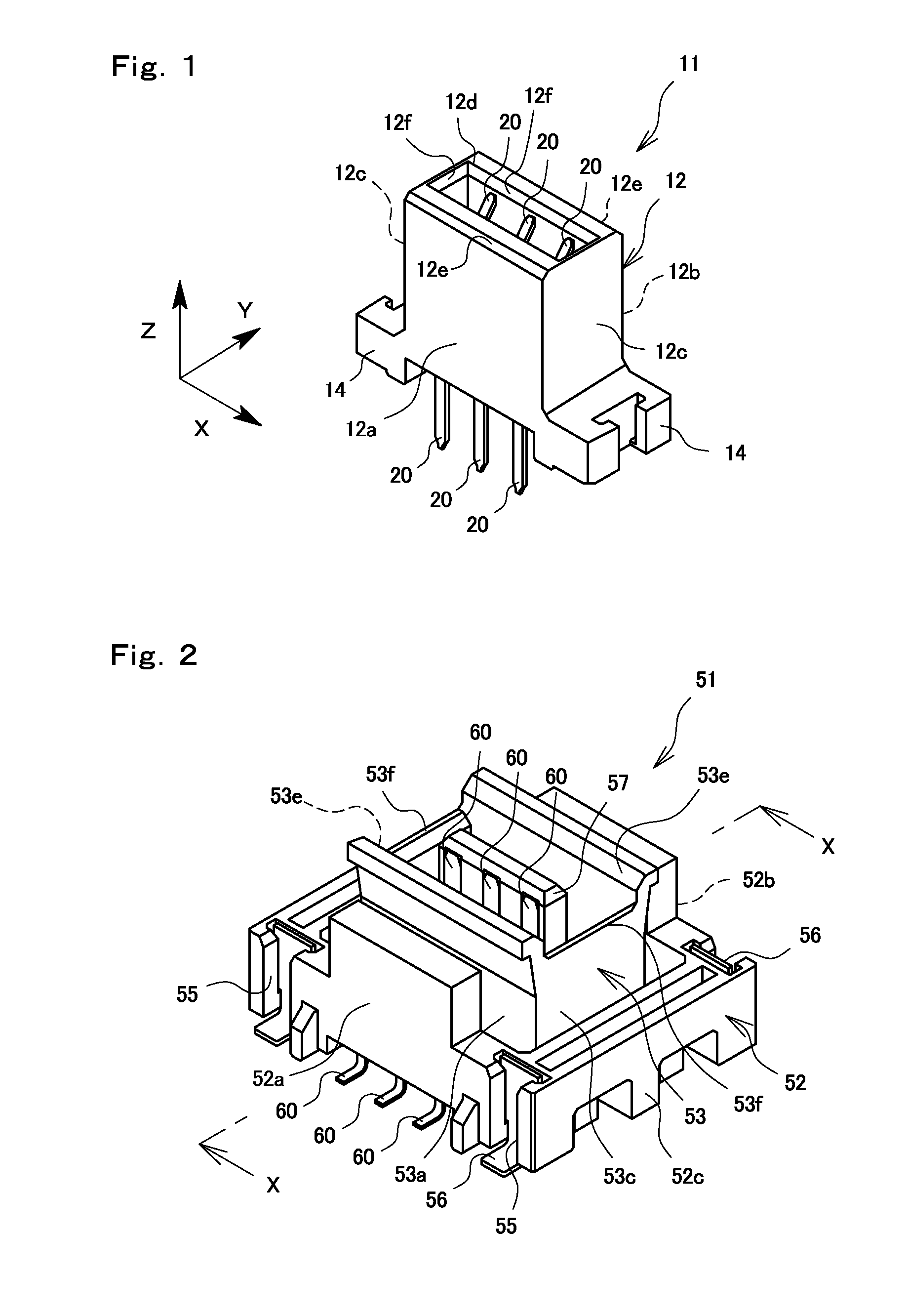
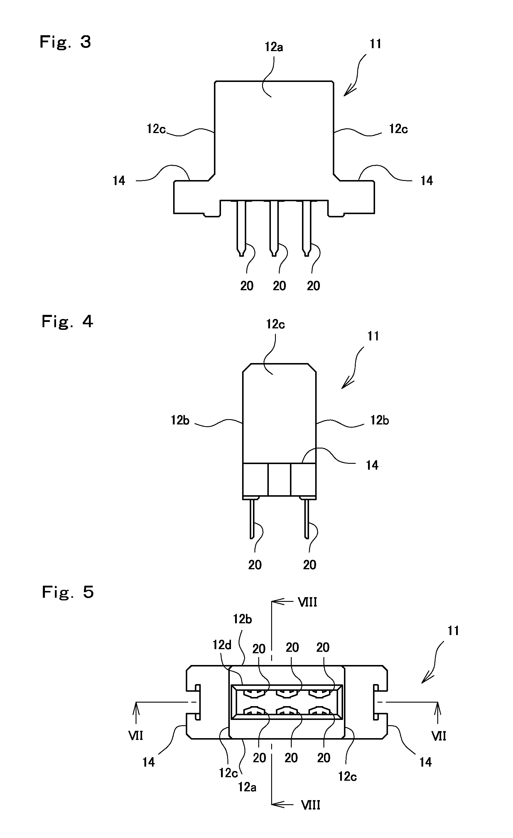
[0056]A connector 11 is illustrated in FIGS. 1 and 3 to 8. FIG. 1 is a perspective view, FIG. 3 is a front view, FIG. 4 is a right side view, FIG. 5 is a plan view, and FIG. 6 is a bottom view. Furthermore, FIGS. 7 and 8 are cross-sectional views of the connector 11. The connector 11 includes a housing 12 and terminals 20 that are illustrated in FIGS. 9A to 9C. The connector 11 is disposed on a connection object member (not shown) such as a printed board, and is fitted to a mating connector 51, such as the one illustrated in FIG. 2, that is disposed on another printed board such that the printed boards are electrically connected to each other.

[0057]In the present description and the claims, as a matter of convenience, in order to distinguish the connectors 11 and 51, the connector 11 is referred to as a socket connector and the connector 51 is referred to as a plug connector or a mating connector. The terminals 20, in the sense that the terminals 20 are terminals ...

second exemplary embodiment

FIG. 15

[0084]Another terminal (a socket terminal) 30 employed in the socket connector 11 is illustrated in FIGS. 15A and 15B.

[0085]The terminal 30 also includes a base portion 31 that is retained by the retaining portion of the housing 12, a rear terminal 33 and a front terminal 34 that extend from the base portion 31, and a connection portion 32 that extends to the side opposite the two arms 33 and 34 from the base portion 31 and that is connected to a conductor on the printed board side.

[0086]Different from the terminal 20 illustrated in the exemplary embodiment described above, the terminal 30 includes a single front spring portion 34b in which no space h is formed in the front terminal 34. However, the terminal 30 is the same as the terminal 20 in that a front contact portion 34a of the front terminal 34 and a rear contact portion 33a of the rear terminal 33 are arranged in the same position with the same width.

[0087]Furthermore, the terminal 30 is the same as the terminal 20 in...

third exemplary embodiment

FIGS. 16 to 18

[0089]Still another exemplary embodiment of the connector 11 and a terminal (a socket terminal) 40 will be illustrated in FIGS. 16A to 18. The terminal 40 also includes a base portion 41, a connection portion 42, a rear terminal 43, and a front terminal 44. Among the above, the rear terminal 43 and the front terminal 44 are different from the terminal 20 of the first exemplary embodiment.

[0090]Similar to the first exemplary embodiment, the front terminal 44 includes a front contact portion 44a including a front contact 44a1 and a distal end portion 44a2, and front spring portions 44b that support the front contact portion 44a so as to allow the front contact portion 44a to be elastically displaced.

[0091]Each front spring portion 44b is formed with long spring piece portions 44b1 and short spring piece portions 44b2, and the long spring piece portions 44b1 are further configured as a multistage spring. Specifically, each front spring portion 44b includes a first bent po...


PUM


Abstract

A terminal used in a connector includes a base portion that is retained in a housing, and a front terminal and a rear terminal that extend from the base portion. A front terminal is provided with a front contact portion that comes in contact with a mating terminal through a flat plate surface of the front contact portion, and a rear terminal is provided with a rear contact portion that comes in contact with a terminal of a mating connector through a flat plate surface of the rear contact portion. The front contact portion and the rear contact portion are arranged at the same position in a width direction.

Description

BACKGROUND OF THE INVENTION[0001]1. Field of the Invention[0002]The present disclosure relates to a terminal and a connector that are fitted into a connection object member such as a printed board and that are used to electrically connect two connection object members to each other.[0003]2. Description of the Related Art[0004]A connector for electrically connecting printed boards to each other includes a plurality of terminals. In a connector provided with a first housing that is disposed on one of the connection object member and a mating connector provided with a second housing that is disposed on the other connection object member, the first housing and the second housing are formed so as to be capable of being fitted to each other, and when fitting the first housing and the second housing together, the corresponding terminals come in contact with each other such that both of the connection object members are electrically connected to each other.[0005]In such connectors, a connec...

Claims


Application Information

Patent Timeline
Patent Type & Authority Applications(United States)
IPC IPC(8): H01R13/11H01R24/60
CPCH01R24/60H01R13/11H01R12/73H01R13/245H01R13/2457
Inventor SAKAUE, JYUNYAOGURA, YOSHIYUKICHIBA, KENSATO, KATSUMASA
Owner IRISO ELECTRONICS CO LTD
Why Eureka
Try Eureka