Electrical connector

a technology of electrical connectors and connectors, applied in the direction of coupling device connections, engagement/disengagement of coupling parts, electrical apparatus, etc., can solve the problems of accidental disengagement of connectors, excessive stress on connections, disengagement of cables and connectors, etc., and achieve the effect of preventing axial disengagement of connectors

Active Publication Date: 2015-11-26
ITT MFG ENTERPRISES LLC
View PDF11 Cites 28 Cited by
  • Summary
  • Abstract
  • Description
  • Claims
  • Application Information

AI Technical Summary

Benefits of technology

[0021]In some embodiments the axial keyway portion enables the mating connector portion to be inserted into the connector keyway in a simple motion.
[0022]The axial keyway portion may be intersected by the circumferential keyway portion between the axial keyway stop and the keyway opening such that the key of the keyed mating connector may be configured to be located at the keyway axial stop when the electrical connector is fully engaged with the mating electrical connector and the pin prevents axial disengagement of the connector by being located on the axial keyway between the key of the keyed mating connector and the keyway opening.

Problems solved by technology

A problem associated with the known breakaway connector arrangement disclosed in U.S. Pat. No. 2,761,111 is that tension on the electrical cable can lead to accidental disengagement of the connectors.
Furthermore, tension applied on the cable for deliberately disengaging the connectors may cause excessive stress on the connections and lead to damage.
However such breakaway connectors as shown in U.S. Pat. No. 2,761,111 and GB 2477987 generally have a problem in that a sufficient applied force or force applied in a specific direction, such as an accidental collision, may disengage the cable and connector.

Method used


Image

  • Electrical connector
  • Electrical connector
  • Electrical connector

Examples


Embodiment Construction

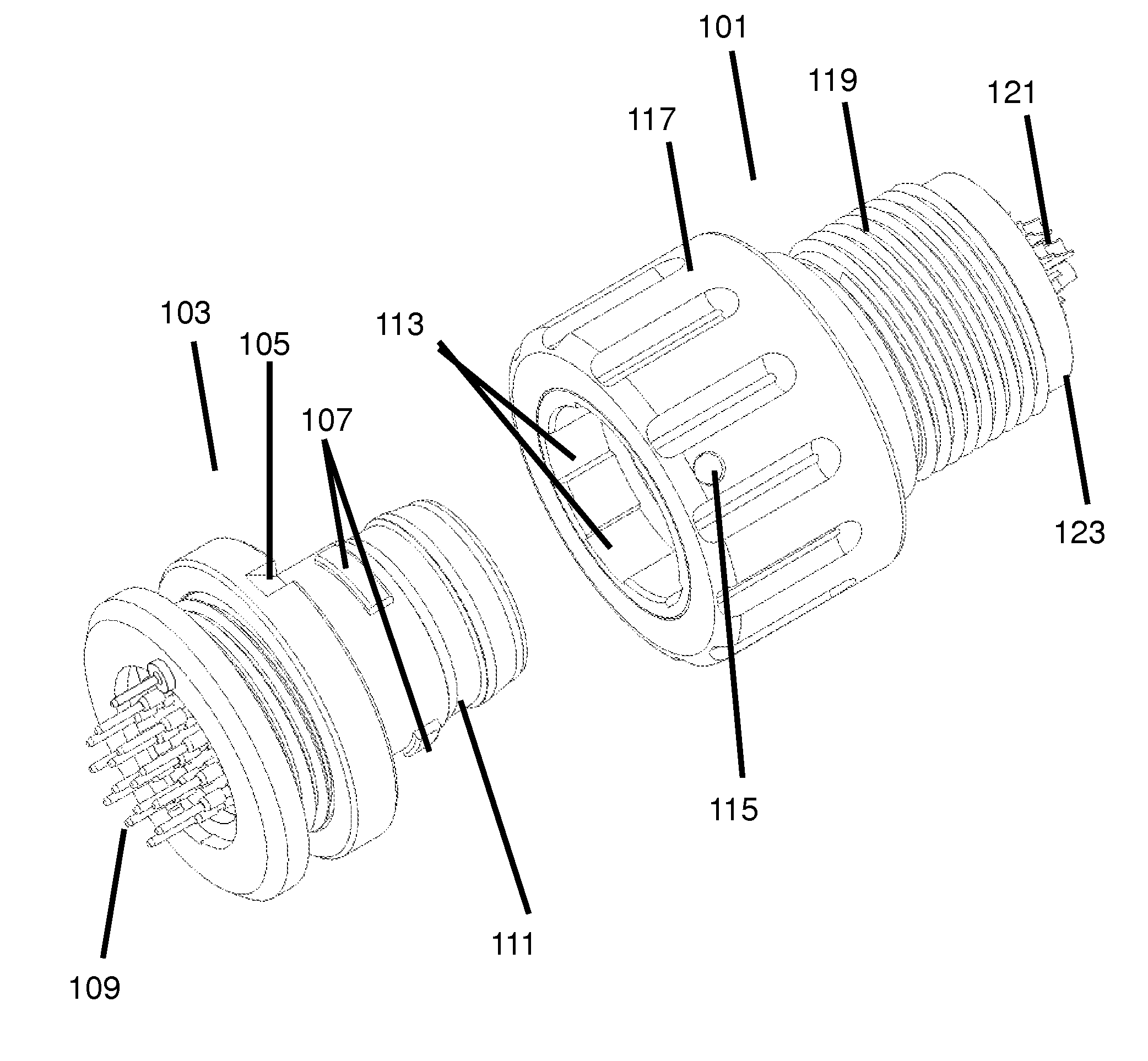
[0058]The invention provides a locking electrical connector for terminating an electrical cable and for engaging with a mating electrical connector.

[0059]The invention provides various modifications to the applicant's previous design of GB 2 477 987 to make the design suitable for locking. The particular problem of connections is that movement in use, and the likelihood of knocking the connection against other objects, means that accidental disconnection is more likely than in static situations.

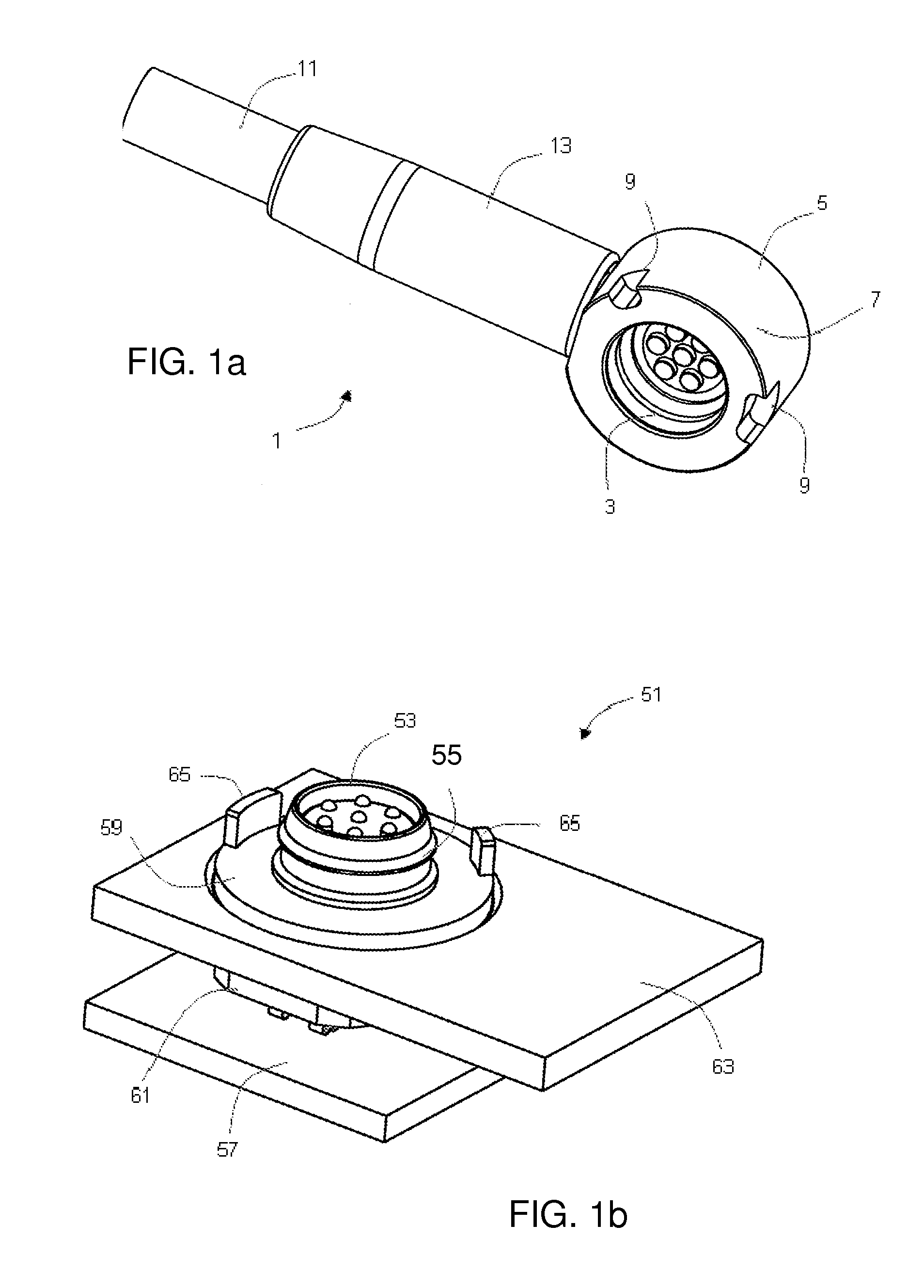
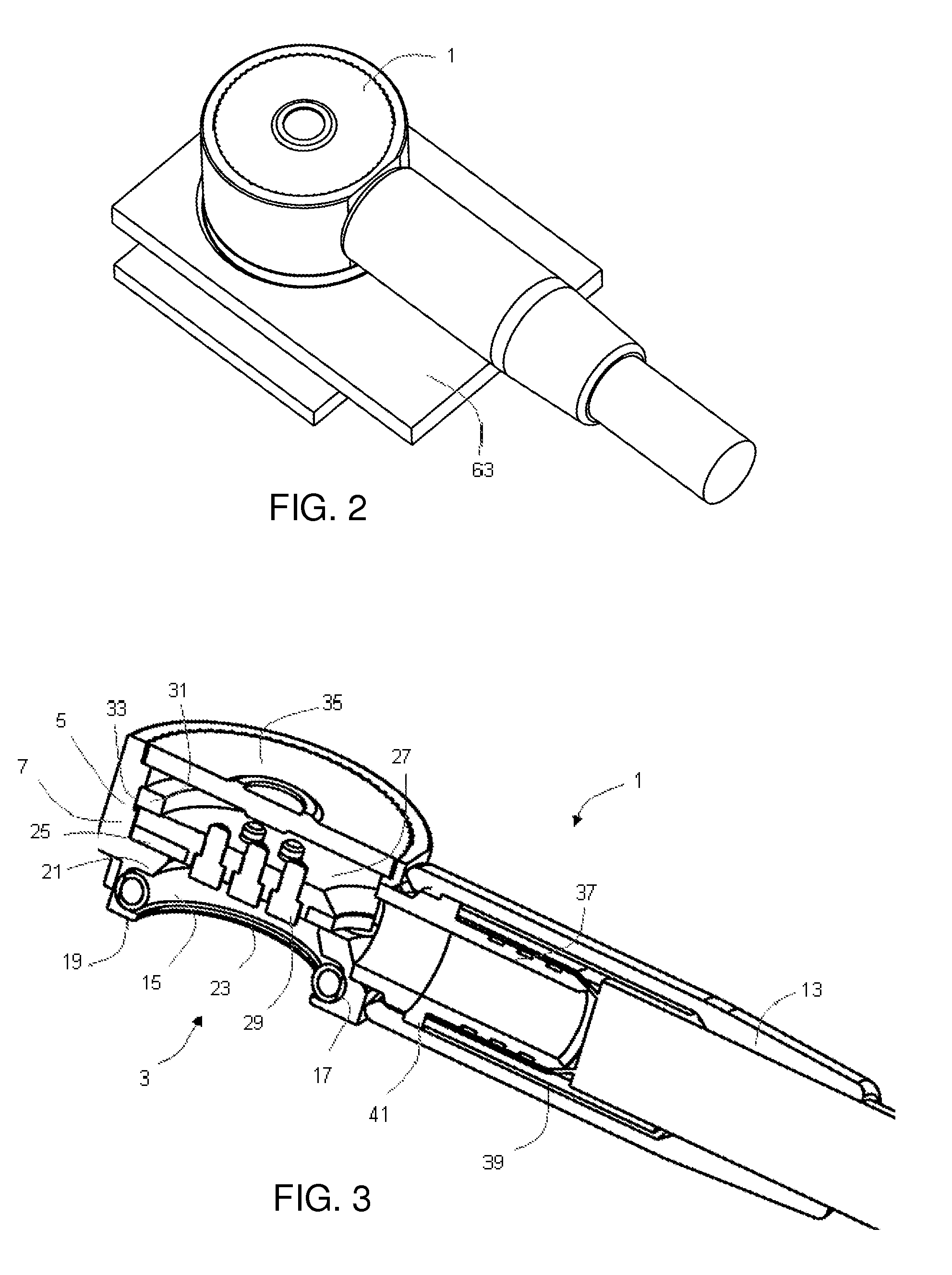
[0060]The design of GB 2 477 987 will first be described, using FIGS. 1 to 4 from GB 2 477 987. Further details can be found in GB 2 477 987.

[0061]FIG. 1a shows the underside of the known angled electrical connector 1. The angled connector 1 is a female connector having a receptacle 3 for receiving a male connector (not shown in FIG. 1a). A plurality of elongate electrical contacts is arranged within the receptacle 3.

[0062]The angled connector 1 comprises a metallic outer body 5 and has an en...


PUM


Abstract

An electrical connector for terminating an electrical cable and for engaging with a mating electrical connector comprises a body, resilient member, and a collar. The body has an engagement portion including a sleeve which extends in a longitudinal direction for engaging with the mating electrical connector. The sleeve comprises a keyway configured to receive a keyed mating connector. The resilient member is arranged on the sleeve and can deform in a transverse direction perpendicular to the direction and provide a reaction force for maintaining the engagement of the connector with the mating connector. The collar is configured to rotate about the sleeve, and comprises a radially inwardly protruding pin which extends into the sleeve and can be moved between two positions. One position is within the keyway between the key of the mating connector and the keyway opening such that the pin prevents axial disengagement of the connector.

Description

CROSS-REFERENCE TO RELATED APPLICATIONS[0001]This application claims priority under 35 U.S.C. §119(a) to GB1409239.9, which is entitled “Electrical Connector” and was filed May 23, 2014 in UK Intellectual Property Office. The entirety of the aforementioned application is incorporated by reference herein.TECHNICAL FIELD[0002]This invention relates to an electrical connector for terminating an electrical cable, such as a shielded cable. In particular, the invention relates to a so-called locking “breakaway” connector, which can be firmly engaged with a mating connector and locked into position to prevent accidental disengagement but can be quickly and easily disengaged when required.BACKGROUND[0003]U.S. Pat. No. 2,761,111 discloses a known breakaway electrical connector for terminating an electrical cable. The electrical connector is arranged to be mechanically engagable with a mating electrical connector to provide an electrically conductive path from the electrical cable to the mati...

Claims


Application Information

Patent Timeline
Patent Type & Authority Applications(United States)
IPC IPC(8): H01R13/629
CPCH01R13/629H01R13/622H01R13/6277H01R13/639H01R13/6456H01R13/62
Inventor JORDAN, PETER
Owner ITT MFG ENTERPRISES LLC
Why Eureka
Try Eureka