Power tool and rotary impact tool

a technology of rotary impact and power tool, which is applied in the direction of manufacturing tools, portable power-driven tools, portable drilling machines, etc., can solve the problems of affecting devices and the like mounted on the circuit board, and achieve the effect of suppressing the transmission of vibration

Active Publication Date: 2015-12-03
MAKITA CORP
View PDF4 Cites 35 Cited by
  • Summary
  • Abstract
  • Description
  • Claims
  • Application Information

AI Technical Summary

Benefits of technology

[0009]In view of the above, an object of the present invention is to provide a power tool and a rotary impact tool capable of suppressing the transmission of vibration from the drive portion as a vibration generation source with respect to the circuit board and so on.
[0031]According to the embodiment of the present invention, there is an advantage that it is possible to provide the power tool and the rotary impact tool capable of suppressing the transmission of vibration with respect to the control circuit board and so on.
[0032]Further, according to the embodiment of the present invention, there is an advantage that it is possible to provide the compact power tool and the rotary impact tool capable of performing deceleration sufficiently.

Problems solved by technology

Therefore, vibration generated in a drive portion connecting to the motor may reach the circuit board through the hand grip, so that devices and the like mounted on the circuit board may be affected by receiving the vibration for a long period of time.

Method used


Image

  • Power tool and rotary impact tool
  • Power tool and rotary impact tool
  • Power tool and rotary impact tool

Examples


first embodiment

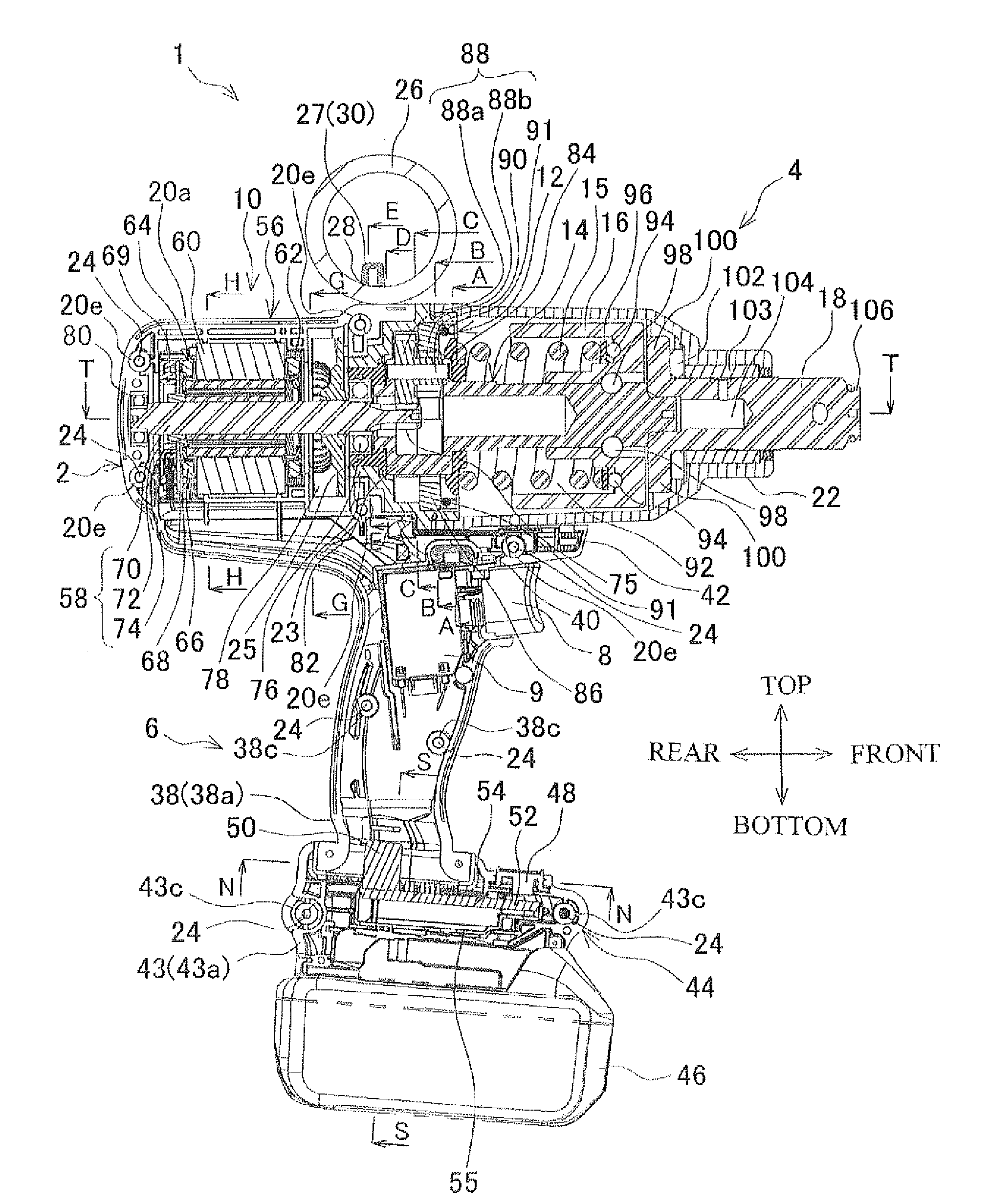
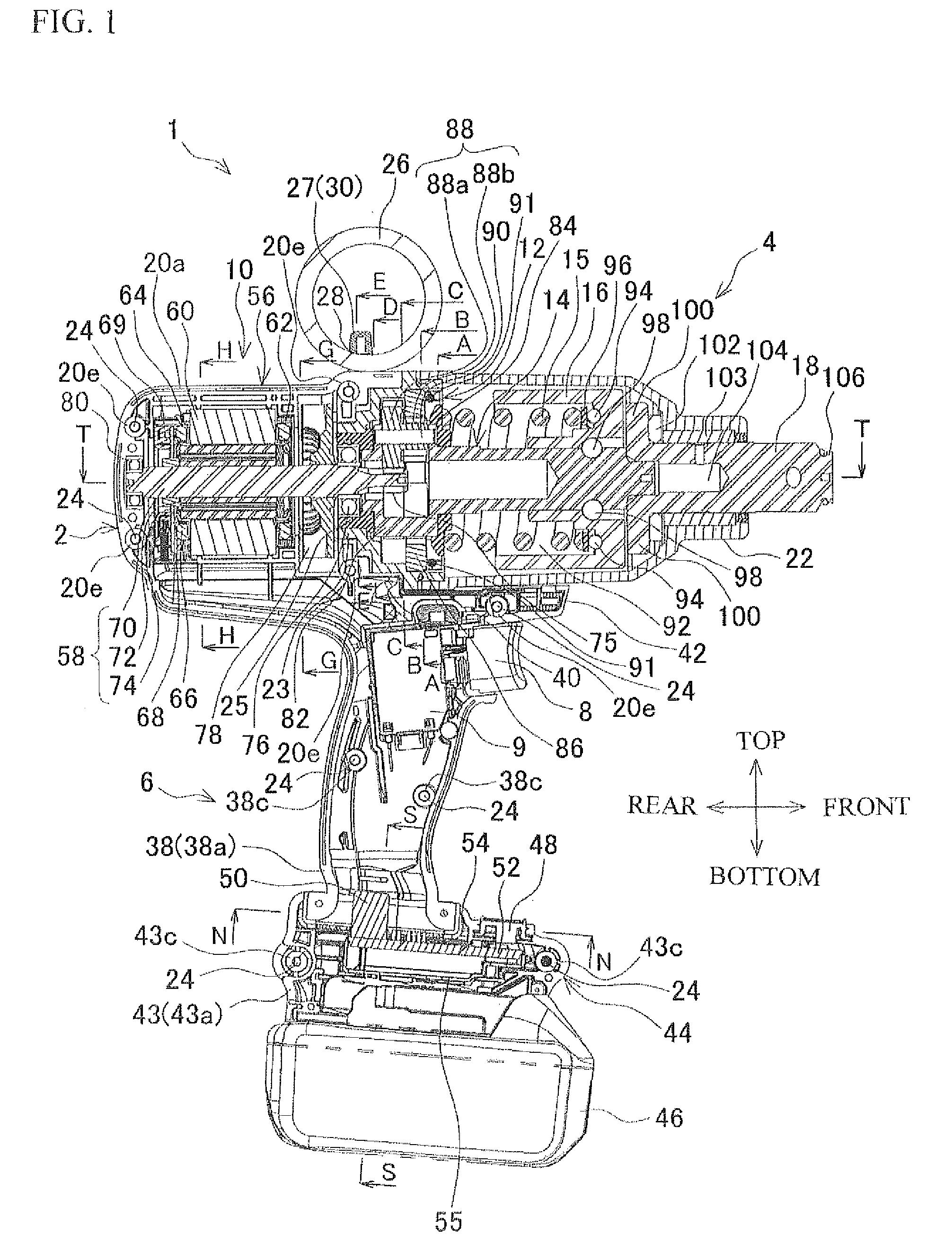
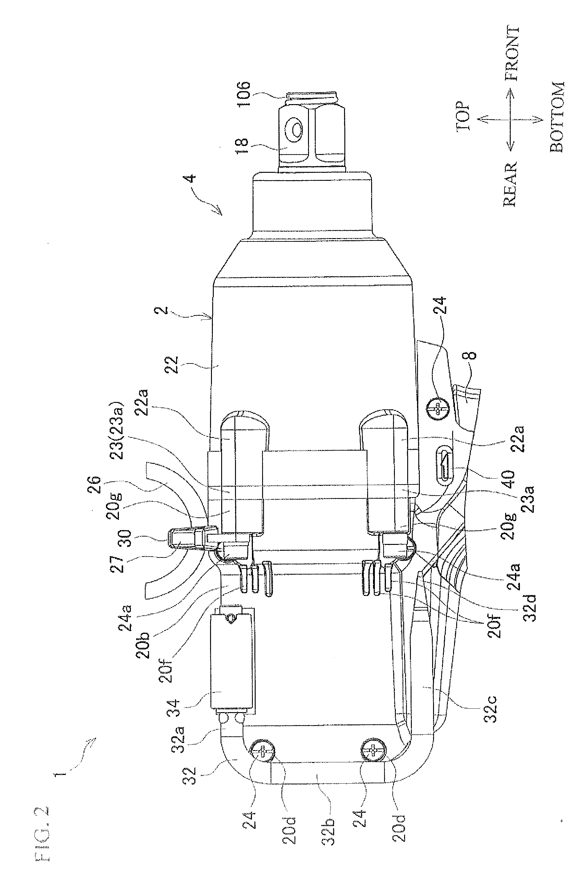
[0058]FIG. 1 is a vertical cross-sectional view taken along the center of a rechargeable impact wrench (rotary impact tool) 1 as an example of a power tool according to a first embodiment of the present invention. FIG. 2 is a partial right side view of the impact wrench 1. FIG. 3 is a top view of the impact wrench 1. FIG. 4 is a top view and a horizontal (T-T line) cross-sectional view of the impact wrench 1. FIG. 5 is a partial rear view of FIG. 1. FIG. 6 is a partial cross-sectional view taken along A-A line of FIG. 1. FIG. 7 is a partial cross-sectional view taken along B-B line of FIG. 1. FIG. 8 is a partial cross-sectional view taken along C-C line of FIG. 1. FIG. 9 is a partial cross-sectional view taken along D-D line of FIG. 1. FIG. 10 is a partial cross-sectional view taken along E-E line of FIG. 1. FIG. 11 is a cross-sectional view taken along G-G line of FIG. 1. FIG. 12 is a cross-sectional view taken along H-H line of FIG. 1. FIG. 13 is a cross-sectional view take along ...

second embodiment

[0144]FIG. 19 is a view of an impact wrench 111 according to a second embodiment of the present invention corresponding to FIG. 1. FIG. 20 is a view of the impact wrench 111 corresponding to FIG. 4. FIG. 21 is a view of the impact wrench 111 corresponding to FIG. 7 (a cross-sectional view taken along BB-BB line of FIG. 19). FIG. 22 is a view of the impact wrench 111 corresponding to FIG. 8 (a cross-sectional view taken along CC-CC line of FIG. 19). FIG. 23 is a view of the impact wrench 111 corresponding to FIG. 13.

[0145]The impact wrench 111 according to the second embodiment has the same structure as the impact wrench 1 according to the first embodiment except for the planetary gear mechanism. The same symbols are given to the same members and portions having the same structures as the impact wrench 1, and the explanation thereof is omitted appropriately.

[0146]A planetary gear mechanism 112 of the impact wrench 111 has the same structure as the planetary gear mechanism 12 of the i...

modification examples

[0162]The present invention is not limited to the above embodiments, and for example, the following modifications can be made appropriately.

[0163]In the planetary mechanism, it is also preferable that the first planetary gear engaged with the pinion gear portion and the second planetary gear engaged with the inter tooth gear are not integrally formed as the front stage and the rear stage of one planetary gear and that the first planetary gear and the second planetary gear are formed separately to be fixed to each other.

[0164]It is also preferable that the pinion gear portion is not provided integrally with the rotor shaft by forming the tip end portion of the rotor shaft in the gear shape and that a separate pinion gear is attached to the tip end portion of the rotor shaft.

[0165]The battery holding housing may be inserted into the grip housing and the elastic body may be interposed therebetween. It is also preferable to interpose the elastic body between the motor housing and the gr...


PUM

PropertyMeasurementUnit
voltageaaaaaaaaaa
voltageaaaaaaaaaa
voltageaaaaaaaaaa

Abstract

To provide a power tool and a rotary impact tool capable of suppressing transmission of vibration to a circuit board and so on from a drive portion connecting to a motor as a vibration generation source. An impact wrench includes a motor housing which houses a motor or a grip housing, a battery holding housing connecting to the motor housing or the grip housing through an elastic body and a control circuit board housed in the battery holding housing for controlling the motor.

Description

[0001]This application claims the benefit of Japanese Patent Application Numbers 2014-109288 and 2014-109289 filed on May 27, 2014, the entirety of which is incorporated by reference.BACKGROUND OF THE INVENTION[0002]1. Field of the Invention[0003]The present invention relates to a power tool capable of applying a rotational force to an output portion and a rotary impact tool capable of applying a rotational impact force to the output portion.[0004]2. Description of Related Art[0005]As disclosed in Japanese Patent Application Publication No. 2011-45201 (JP 2011-45201-A), an impact driver which transmits the rotation of a drive rotation shaft of a motor to an output shaft after decelerating the rotation has been known.[0006]In such impact driver, a circuit board is housed in a lower end portion of a hand grip connecting to a motor housing, and a battery attaching portion is provided below the lower end portion.[0007]Further, in the impact driver, the rotation is decelerated by a plane...

Claims


Application Information

Patent Timeline
Patent Type & Authority Applications(United States)
IPC IPC(8): B25B21/02B25F5/00
CPCB25F5/00B25B21/02
Inventor KONDO, TOMOYUKIHIRABAYASHI, TOKUO
Owner MAKITA CORP
Why Eureka
Try Eureka