Liquid ejecting apparatus, control method of liquid ejecting head, and control method of liquid ejecting apparatus

a liquid ejecting apparatus and control method technology, applied in the direction of printing, other printing apparatus, etc., can solve the problems of difficult to discharge the air bubbles inside the liquid in the nozzle, air bubbles are also likely to enter the liquid, etc., to reduce the unnecessary consumption of liquid and efficiently discharge the air bubbles inside the liquid

Active Publication Date: 2015-12-03
SEIKO EPSON CORP
View PDF2 Cites 8 Cited by
  • Summary
  • Abstract
  • Description
  • Claims
  • Application Information

AI Technical Summary

Benefits of technology

[0009]An advantage of some aspects of the invention is to provide a liquid ejecting apparatus, a control method of the liquid ejecting head, and a control method of the liquid ejecting apparatus in which it is possible to reduce the unnecessary consumption of the liquid and to efficiently discharge the air bubbles inside the liquid in the nozzle.
[0011]According to one aspect of the invention, it is possible to suppress the unnecessary consumption of the liquid and to discharge the air bubbles inside the liquid in the nozzle. Specifically, the maintenance process is performed on the nozzle that is detected as being abnormal to restrain the unnecessary maintenance process from being performed. Further, since the air bubbles inside the liquid in the nozzle hardly float to the pressure chamber in the ejecting operation based on the maintenance drive waveform which is applied in at least a first time, it is possible to efficiently discharge the air bubbles with the liquid in the nozzle. Therefore, the consumption of the liquid can be largely suppressed, compared with the maintenance process of the related art.
[0016]According to the configuration described above, since a relatively greater amount of the liquid for one time can be ejected from the nozzle and the pressure variation in the pressure chamber goes along slowly during the ejecting operation, compared with the drive waveform which causes the small liquid droplet to be ejected, the unnecessary vibration is hardly generated in the pressure chamber and it is possible to more efficiently discharge the air bubbles from the nozzle.

Problems solved by technology

Furthermore, when the liquid thickened in the vicinity of the nozzle is ejected, the air bubbles are also likely to enter into the liquid.
However, in the flushing process of the related art, it is difficult to discharge the air bubbles inside the liquid in the nozzle.
Specifically, the maintenance process is performed on the nozzle that is detected as being abnormal to restrain the unnecessary maintenance process from being performed.

Method used


Image

  • Liquid ejecting apparatus, control method of liquid ejecting head, and control method of liquid ejecting apparatus
  • Liquid ejecting apparatus, control method of liquid ejecting head, and control method of liquid ejecting apparatus
  • Liquid ejecting apparatus, control method of liquid ejecting head, and control method of liquid ejecting apparatus

Examples


Embodiment Construction

[0030]Hereinafter, embodiments of the invention will be described with reference to the accompanying drawings. The embodiments described below are limited to concretely preferable examples of the invention in various manners. However, the scope of the invention is not limited to these embodiments unless otherwise stated particularly for limiting the invention. Further, hereinafter, an ink jet type recording apparatus (hereinafter referred to as a printer) will be described as an example of the liquid ejecting apparatus according to one aspect of the invention.

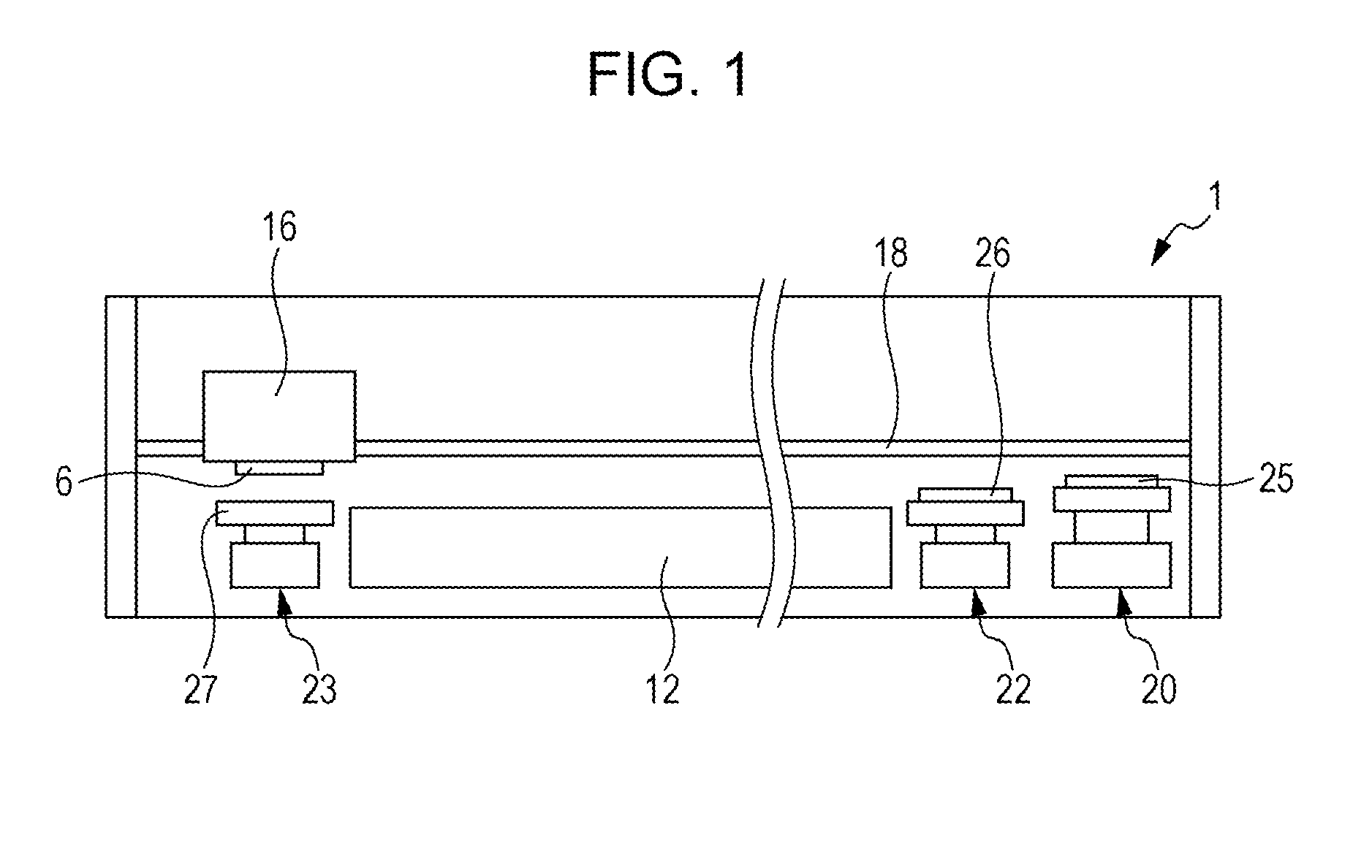
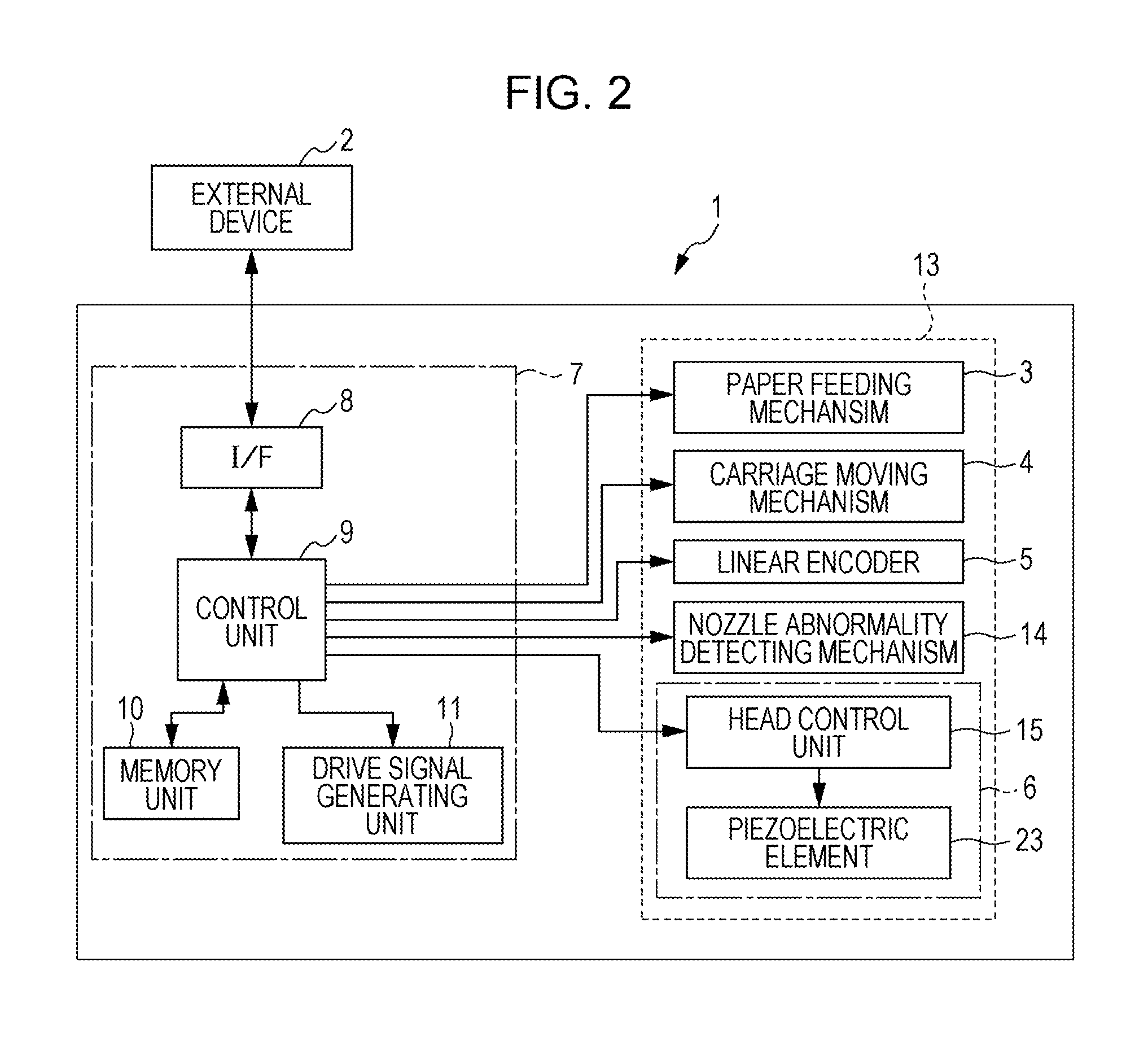
[0031]FIG. 1 is a front view explaining an internal configuration of a printer 1, and FIG. 2 is a block diagram for explaining an electrical configuration of the printer 1. The printer 1 according to the embodiment is electrically connected to, for example, an external device 2 such as electric equipment of an computer and the like in wireless or wired manner, and receives printing data for reflecting an image or a text and the...


PUM


Abstract

When a nozzle abnormality detecting mechanism detects an abnormality of the nozzle, in the maintenance process of causing the drive waveform to be applied plural times to the actuator corresponding to the nozzle that the detecting mechanism detects as being abnormal, and thereby causing the ejecting operation to be performed, at least a first-time drive waveform applied to the actuator is a flushing pulse which causes a meniscus in the nozzle not to be positively attracted from an initial position to the pressure chamber, but causes the meniscus to be extruded to the ejection side and thereby causes the liquid to be ejected from the nozzle.

Description

CROSS REFERENCE TO RELATED APPLICATIONS[0001]This application claims priority to Japanese Patent Application No. 2014-109721 filed on May 28, 2014. The entire disclosure of Japanese Patent Application No. 2014-109721 is hereby incorporated herein by reference.BACKGROUND[0002]1. Technical Field[0003]The present invention relates to a liquid ejecting apparatus such as an ink jet type recording apparatus, a control method of a liquid ejecting head mounted in the liquid ejecting apparatus, and a control method of the liquid ejecting apparatus. Particularly, the invention relates to a liquid ejecting apparatus a control method of the liquid ejecting head and a control method of the liquid ejecting apparatus that perform a maintenance process in which a liquid is ejected from nozzles and ejection performance of the liquid ejecting head is restored.[0004]2. Related Art[0005]A liquid ejecting apparatus includes a liquid ejecting head to eject (discharge) various types of liquid from the liq...

Claims


Application Information

Patent Timeline
Patent Type & Authority Applications(United States)
IPC IPC(8): B41J2/045
CPCB41J2/0451B41J2/04586B41J2/04588B41J2/04581B41J2/165B41J2/16526B41J2/16579
Inventor ZHANG, JUNHUA
Owner SEIKO EPSON CORP
Why Eureka
Try Eureka