Antenna

a technology of antenna arrays and antennas, applied in the field of antennas, can solve problems such as the increase in the size of the entire apparatus, and achieve the effect of excellent side-lobe suppression characteristics

Inactive Publication Date: 2015-12-03
NEC CORP
View PDF13 Cites 139 Cited by
  • Summary
  • Abstract
  • Description
  • Claims
  • Application Information

AI Technical Summary

Benefits of technology

[0008]According to the present invention, it is possible to provide

Problems solved by technology

However, when the parabola antenna satisfies the side-lobe standards, the thickness of

Method used


Image

  • Antenna
  • Antenna
  • Antenna

Examples


first exemplary embodiment

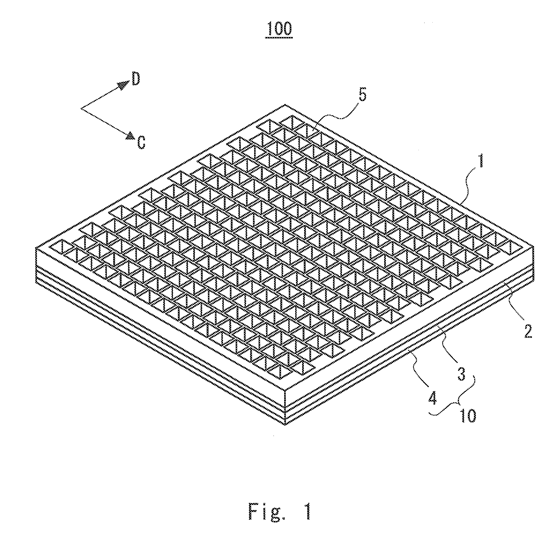
[0017]First, an antenna 100 according to an exemplary embodiment will be described. FIG. 1 is a perspective view schematically showing the configuration of the antenna 100. The antenna 100 includes an antenna layer 1, a coupling layer 2, a waveguide layer 3, and a bottom layer 4. The antenna layer 1, the coupling layer 2, the waveguide layer 3, and the bottom layer 4 are each formed of, for example, a metal. The waveguide layer 3 and the bottom layer 4 constitute a feeder circuit layer 10.

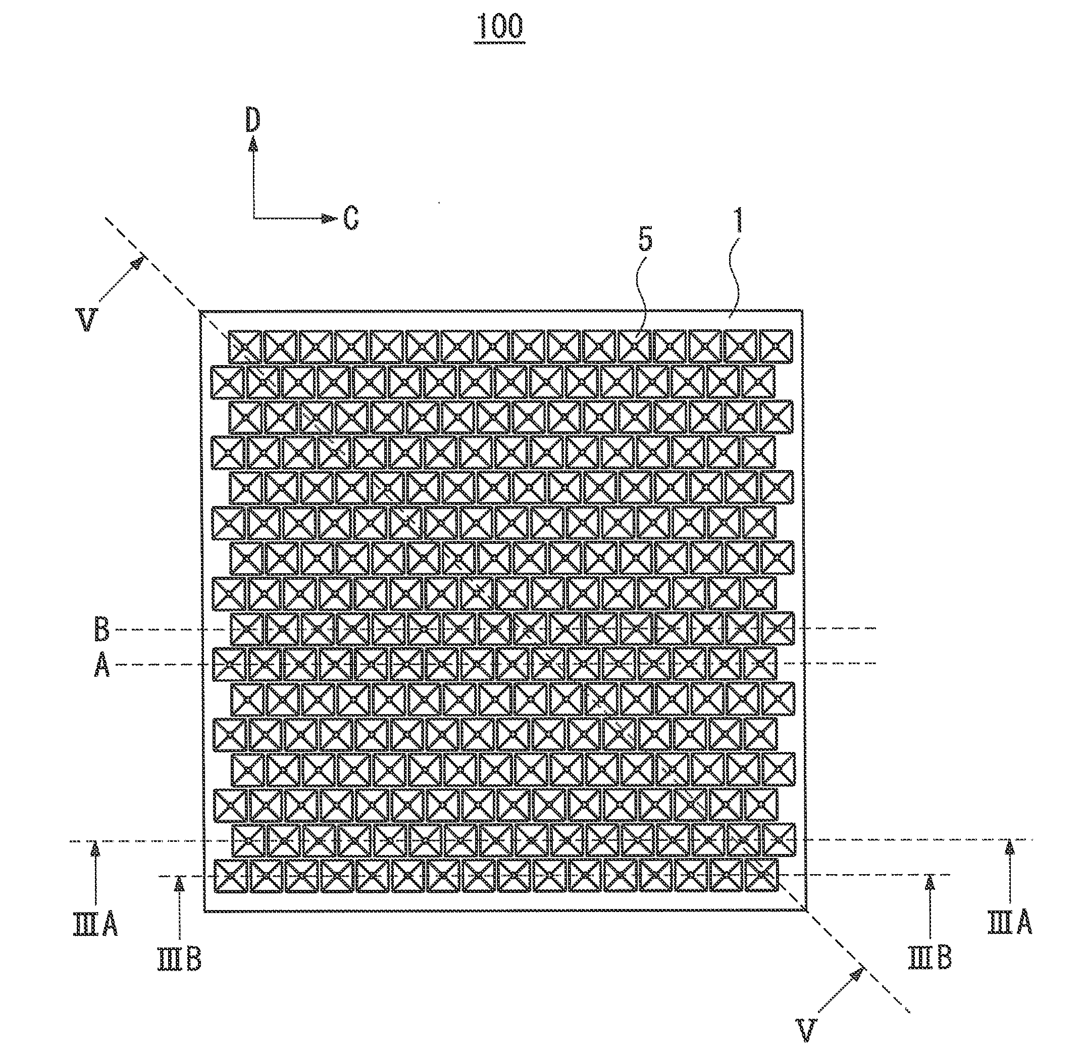
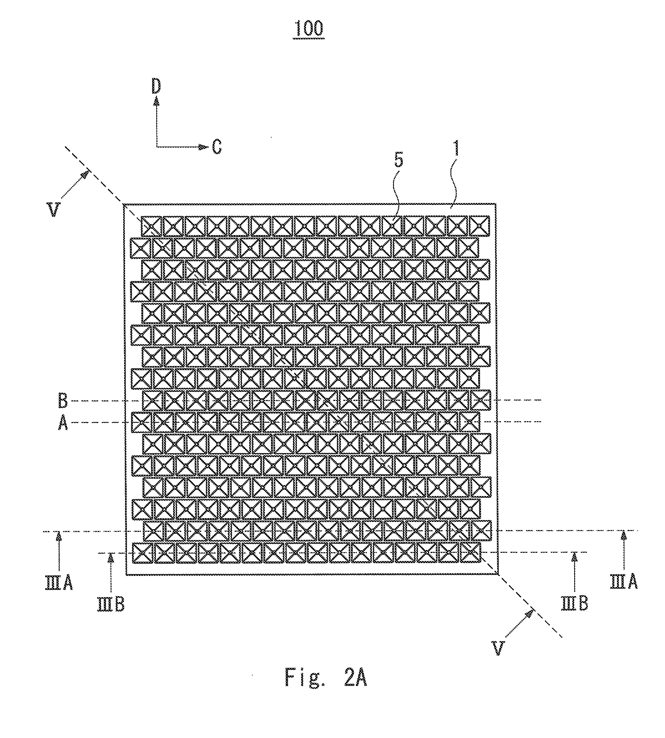
[0018]FIG. 2A is a top view schematically showing the configuration of the antenna 100. In the antenna layer 1, horn antennas 5 each having a quadrangular pyramid shape are arranged in a staggered manner. Hereinafter, the horn antennas are also referred to simply as antenna elements. The horn antennas in adjacent rows are each arranged with an offset. In this exemplary embodiment, the horn antennas 5 arranged in a row B shown in FIG. 2A are offset in a direction C (also referred to as a first direc...


PUM


Abstract

An antenna includes an antenna layer, a coupling layer, and a feeder circuit layer. The antenna layer includes antennas elements. First and second antennas elements are arranged in such a manner that the centers thereof are aligned in a first direction. A third antenna element is arranged in such a manner that the third antenna element is separated from the first antenna element in a second direction and centers of the antennas elements are not aligned in the second direction. A waveguide is formed in the coupling layer.

Description

TECHNICAL FIELD[0001]The present invention relates to an antenna.BACKGROUND ART[0002]Side-lobe characteristics which are required for antennas used in radio systems, such as point-to-point, are specified in international standards, and it is necessary to suppress the side lobe level to be lower than a predetermined level. Typical international standards are ETSI (European Telecommunications Standards Institute) standards.[0003]A parabola antenna is generally used as an antenna for point-to-point communication. However, when the parabola antenna satisfies the side-lobe standards, the thickness of the antenna increases, which results in an increase in the size of the entire apparatus. For this reason, a planar antenna is desired.[0004]In a millimeter wave band, a planar antenna including a waveguide with a transmission loss lower than that of a microstrip line is used. As a configuration of such a planar antenna, a configuration in which horn antennas are arranged in an array is known...

Claims


Application Information

Patent Timeline
IPC IPC(8): H01Q1/50H01Q1/36H01Q13/02
CPCH01Q1/50H01Q1/36H01Q13/02H01Q21/0006H01Q21/0087H01Q21/064H01Q21/06
Inventor IWANAKA, DAISUKE
Owner NEC CORP
Why Eureka
Try Eureka