An apparatus and method for manufacturing a steel component

a technology of structural framing components and manufacturing methods, applied in the direction of manufacturing tools, load-supporting pillars, edge grinding machines, etc., can solve the problems of dangerous sharp edges, serious drawbacks of the known method of roll forming steel components, and the products produced by the method, and achieve the effect of fast and economical manner

Inactive Publication Date: 2015-12-10
POLIQUIN RICHARD
View PDF49 Cites 5 Cited by
  • Summary
  • Abstract
  • Description
  • Claims
  • Application Information

AI Technical Summary

Benefits of technology

[0015]Various embodiments of the subject invention provide a steel structural framing component that is safe to the touch, particularly in areas in which they are likely to be contacted by workers. Other embodiments describe a method of manufacturing the steel component in a fast and economical manner.

Problems solved by technology

Known methods of roll forming steel components, and the products these methods produce, suffer serious drawbacks, particularly with regard to various safety concerns during manufacture, and with the resulting final product.
In the steel structural component forming industry, known methods of forming steel components leave the lips and edges dangerously sharp, with numerous burs and / or surfaces that are capable of injuring not only the manufacturing engineers that handle them, but also the on-site construction workers who are responsible for constructing the components for which they were ultimately formed.
Furthermore, particularly in relation to steel studs, current safeguards are unduly expensive, and are also wasteful of raw materials.
However to hem, the manufactures must use additional raw materials, which is expensive and wasteful, since the hem does not contribute to structural integrity.

Method used


Image

  • An apparatus and method for manufacturing a steel component
  • An apparatus and method for manufacturing a steel component
  • An apparatus and method for manufacturing a steel component

Examples


Embodiment Construction

[0032]The present invention is best understood by reference to the detailed figures and description set forth herein.

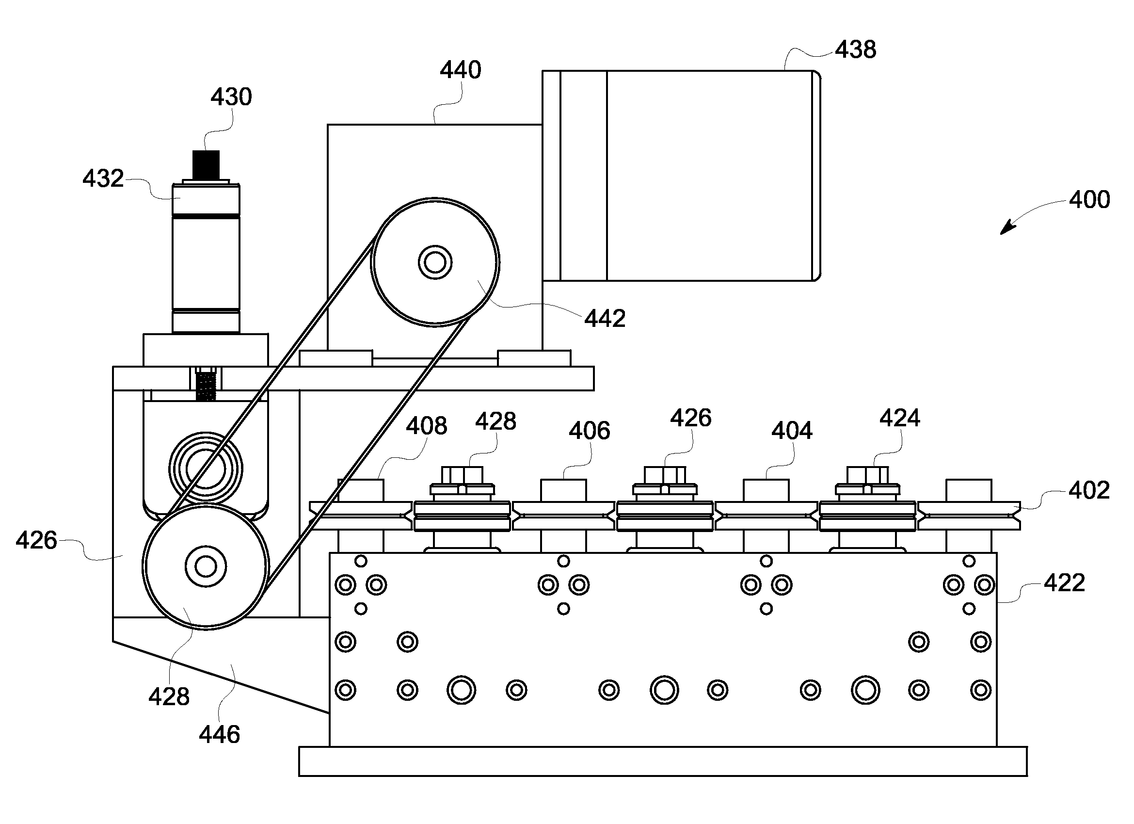
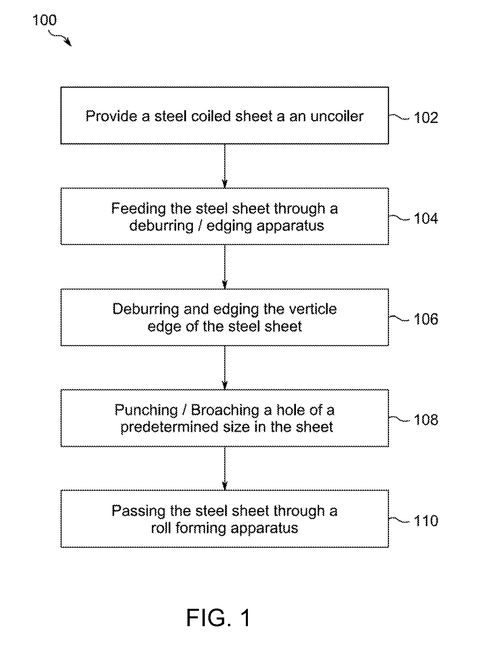
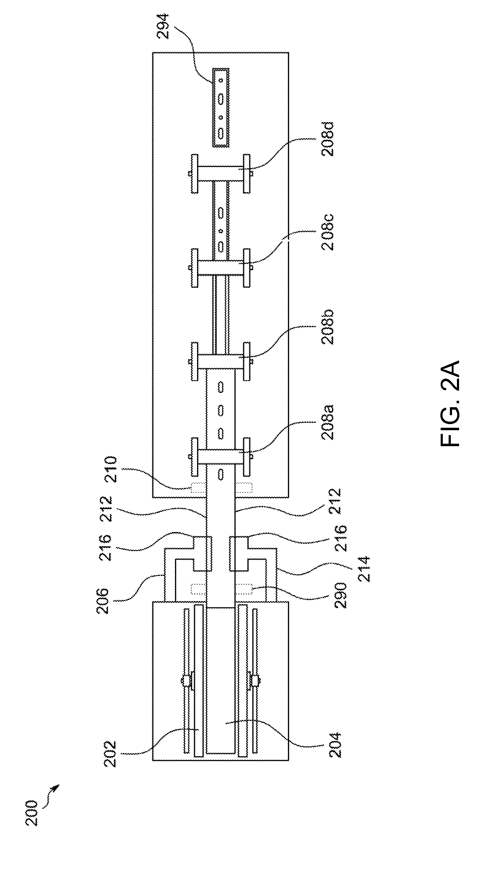
[0033]Embodiments of the invention are discussed below with reference to the Figures. However, those skilled in the art will readily appreciate that the detailed description given herein with respect to these figures is for explanatory purposes as the invention extends beyond these limited embodiments. For example, it should be appreciated that those skilled in the art will, in light of the teachings of the present invention, recognize a multiplicity at alternate and suitable approaches, depending upon the needs of the particular application, to implement the functionality of any given detail described herein, beyond the particular implementation choices in the following embodiments described and shown. For example, while steel studs are primarily referred to herein, it will be appreciated that other steel components such as floor joists, roof rafters, and tracks are ...


PUM

PropertyMeasurementUnit
temperatureaaaaaaaaaa
linear forceaaaaaaaaaa
motive forceaaaaaaaaaa

Abstract

An apparatus for edging a steel component, the apparatus having at least one edger roll (402, 404, 406) mounted to a slider housing (422) and a feed housing connected to the slider housing, wherein the feed housing is configured to drive the steel component through the at least one edger roll, and wherein the edger roll is adjustably mounted to the slider housing.

Description

CROSS-REFERENCE TO RELATED APPLICATIONS[0001]This application is a continuation in part of Application No. PCT / US2013 / 038529 filed Apr. 29, 2013.[0002]Application No. PCT / US2013 / 038529 claimed the priority benefit of the U.S. provisional application for patent Ser. No. 61 / 753,157 filed on Jan. 16, 2013, entitled A Steel Component and Method of Making the Same. The contents of this related provisional application are incorporated herein by reference for all purposes.STATEMENT REGARDING FEDERALLY SPONSORED RESEARCH OR DEVELOPMENT [0003]Not ApplicableREFERENCE TO SEQUENCE LISTING, A TABLE, OR A COMPUTER PROGRAM LISTING COMPACT DISK APPENDIX[0004]Not ApplicableBACKGROUND OF THE INVENTION[0005]This application relates generally to structural framing components, steel framing components, and an apparatus and method for making the same. More particularly, the application relates to an apparatus and method to manufacture edged or deburred steel steel studs, tracks, joints and edges.[0006]St...

Claims


Application Information

Patent Timeline
Patent Type & Authority Applications(United States)
IPC IPC(8): B24B9/04B21D19/00B21D5/06
CPCB24B9/04B21D19/005B21D5/06E04C2003/0473C23C2/00B21B1/22B21C47/16B21D35/001B21D47/01
Inventor POLIQUIN, RICHARD
Owner POLIQUIN RICHARD
Why Eureka
Try Eureka