Touch display device

a display device and touch technology, applied in non-linear optics, instruments, optics, etc., can solve the problems of adversely affecting the quality of displayed images and affecting the overall optical properties of the touch display devi

Active Publication Date: 2015-12-10
TPK UNIVERSAL SOLUTIONS
View PDF3 Cites 45 Cited by
  • Summary
  • Abstract
  • Description
  • Claims
  • Application Information

AI Technical Summary

Benefits of technology

This invention provides a new type of touch display screen with improved technology compared to existing devices. It uses special filters called linear polarizers which allow certain types of light to pass through while blocking others. There is also a layer made up of flexible material that controls how much bending or twisting happens for different kinds of light. These features make it possible to create better looking displays with more accurate color representation and reduced glare. Overall, this innovative design solves some common problems associated with traditional screens and makes them easier to use and view.

Problems solved by technology

The technical problem addressed by this patent relates to improving the appearance of touch display devices by reducing the impact on the optical properties caused by differences between the materials used for the various components of the device.

Method used


Image

  • Touch display device
  • Touch display device
  • Touch display device

Examples


Embodiment Construction

[0022]First Touch Display Device

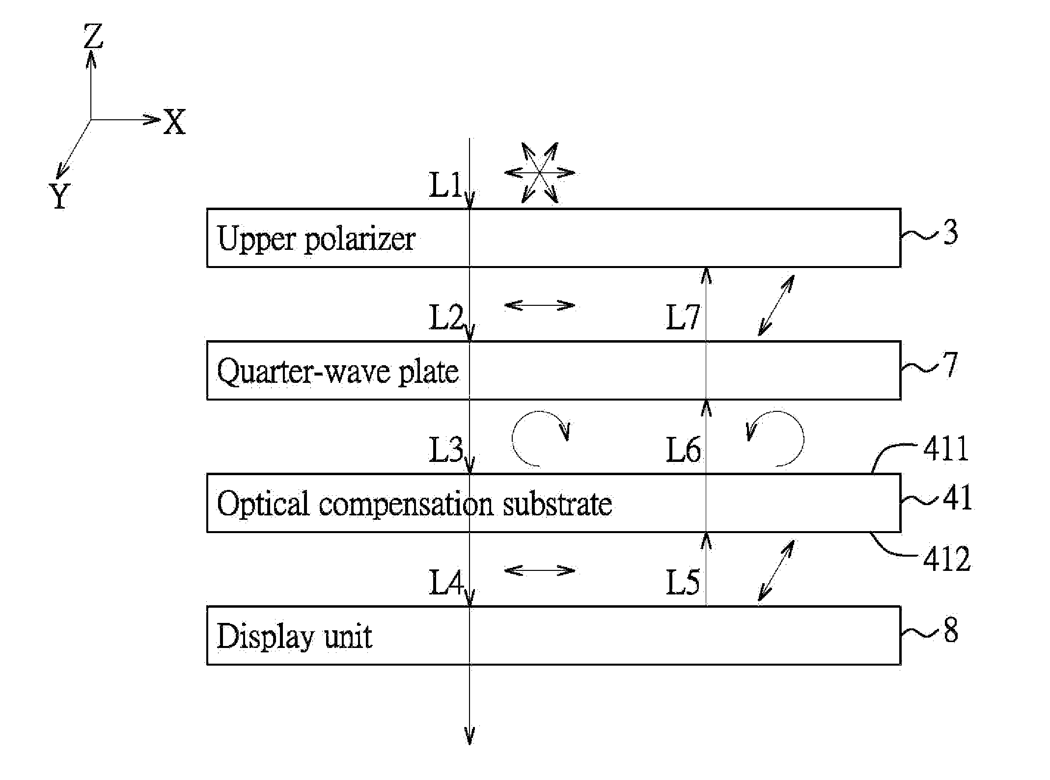
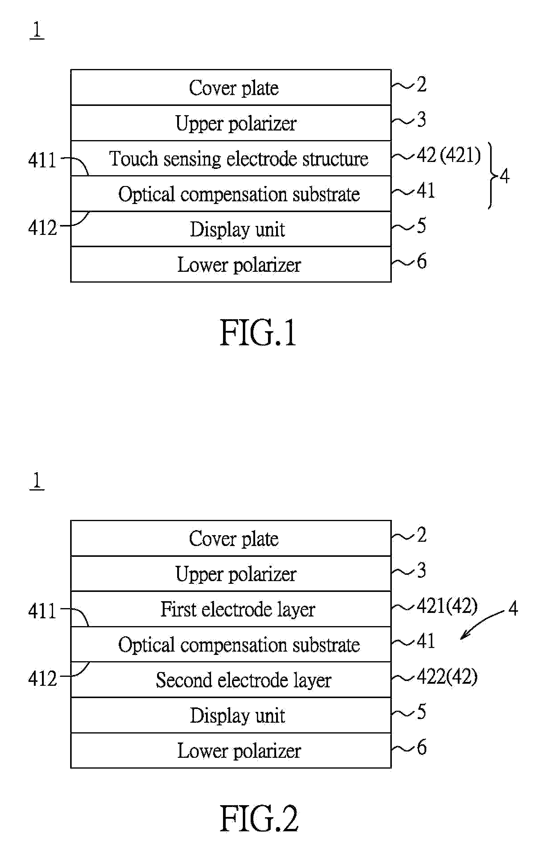
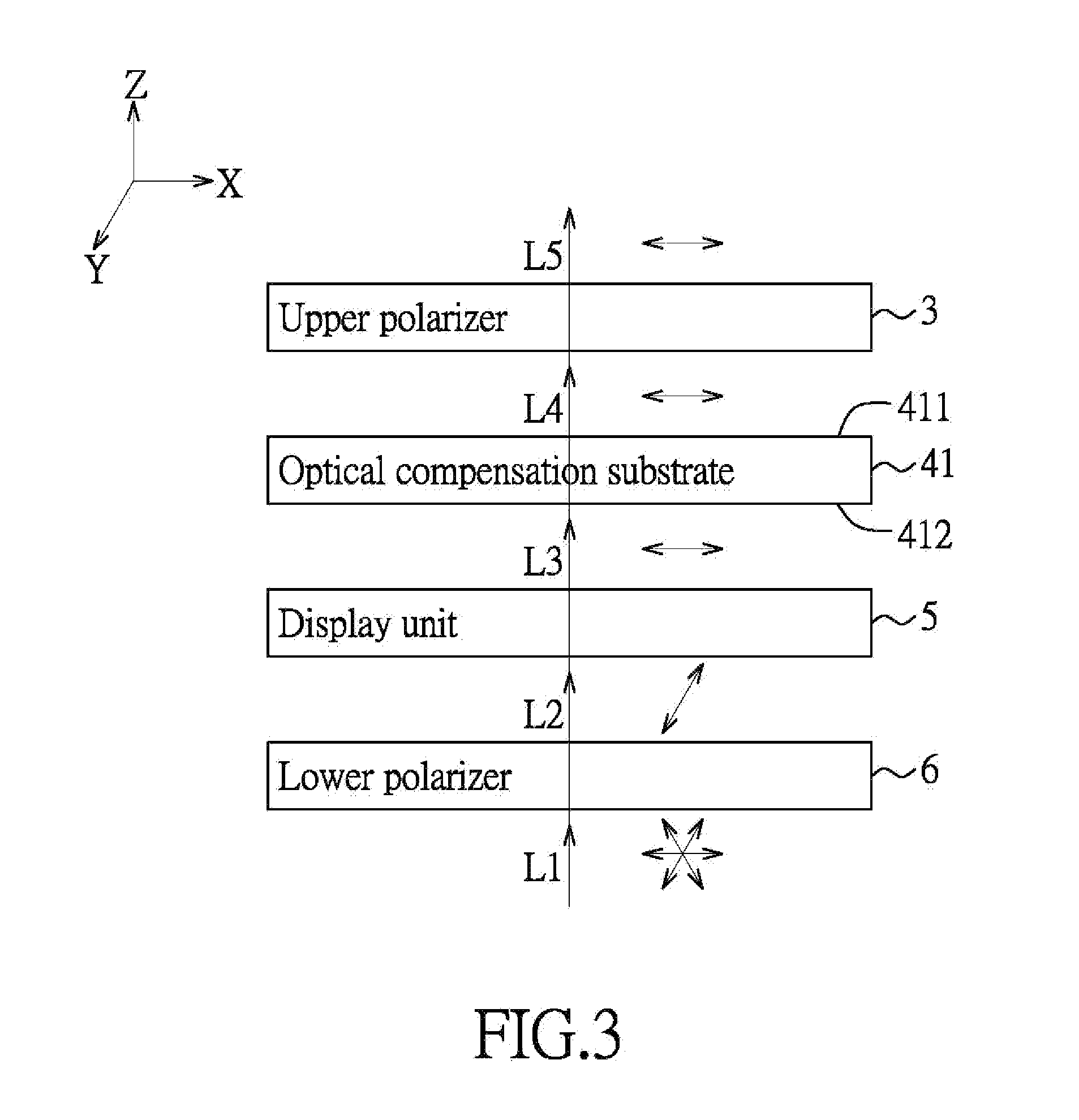
[0023]FIGS. 1, 2 and 3 show a touch display device according to at least one embodiment. In order to conveniently describe the optical properties of light, a first linear polarization direction and a second linear polarization direction which is perpendicular to the first linear polarization direction are defined. For instance, in FIG. 3, the first linear polarization direction is a direction along an X-axis, and is illustrated by a horizontal arrow. The second linear polarization direction is a direction along a Y-axis and is illustrated by an inclined arrow. The traveling direction of light rays (L1 to L5) is along a Z-axis. Moreover, according to the state of use of the touch display device 1, in the following description associated with any element, the term “above” or the like represents a side that is closer to the user in space, while the term “under” or the like represents a side that is more distant from the user in space.

[0024]To be specific...


PUM


Abstract

A touch display device includes an upper polarizer, a display unit and a touch sensing unit. The upper polarizer allows light having a first linear polarization direction to pass therethrough and blocks light having a second linear polarization direction. The second linear polarization direction is perpendicular to the first linear polarization direction. The display unit is spaced-apart from the upper polarizer and is used to display images. The touch sensing unit is disposed between the upper polarizer and the display unit, and includes an optical compensation substrate and a touch sensing electrode structure disposed on the optical compensation substrate. The optical compensation substrate is flexible and is able to control the polarization property of the light passing therethrough.

Description


Claims


Application Information

Patent Timeline
Owner TPK UNIVERSAL SOLUTIONS
Why Eureka
Try Eureka