Liquid crystal display device

a display device and liquid crystal technology, applied in static indicating devices, instruments, optics, etc., can solve the problems of increasing the power consumption of each display image, increasing the size of the source, and not always easily visible images other than specific night scene images such as those described before, so as to reduce power consumption and control luminance, increase and decrease the luminance set value

Active Publication Date: 2015-12-10
FUJIFILM CORP
View PDF4 Cites 10 Cited by
  • Summary
  • Abstract
  • Description
  • Claims
  • Application Information

AI Technical Summary

Benefits of technology

[0011]In the liquid crystal display device of PTL 1, the backlight luminance of the high luminance area is increased as the range of the high luminance area decreases; however, viewability and glare of the display image is greatly affected by a size of a luminance area at middle luminance lower than the high luminance. As a result, in the liquid crystal display device of PTL 1, an image other than a specific night scene image such as that described before is not always easily visible. Particularly in PTL 1, attention is paid only to the high luminance area. Owing to this, in a case where an image including a lot of isolated bright points such as a starry sky is displayed, for example, a display image may be felt to be glaring. In addition, in a case where slide show display, moving image display or the like is performed, the number (ratio) of high luminance areas varies for each of display images, so that a variation of power consumption for each of the display images increases. As a result, power to be supplied to a backlight unit varies depending on the display image to cause a power source to increase in size, thereby increasing manufacturing costs as well as power consumption.

Problems solved by technology

As a result, in the liquid crystal display device of PTL 1, an image other than a specific night scene image such as that described before is not always easily visible.
In addition, in a case where slide show display, moving image display or the like is performed, the number (ratio) of high luminance areas varies for each of display images, so that a variation of power consumption for each of the display images increases.
As a result, power to be supplied to a backlight unit varies depending on the display image to cause a power source to increase in size, thereby increasing manufacturing costs as well as power consumption.
Furthermore, if the upper limit value and the lower limit value of the luminance of each of the segment areas are set as with the liquid crystal display device of PTL 2, merits of the local dimming control that increases the contrast ratio are impaired.
As a result, the image quality of a display image may degrade.
However, if the luminance is set high particularly in a display image with a high average luminance level (hereinafter referred to as APL), that is, in an entirely bright image, the amount of light incident on an eye increases to cause an ill effect that the image is felt to be glaring.

Method used


Image

  • Liquid crystal display device
  • Liquid crystal display device
  • Liquid crystal display device

Examples


first embodiment

Configuration of Tablet Terminal

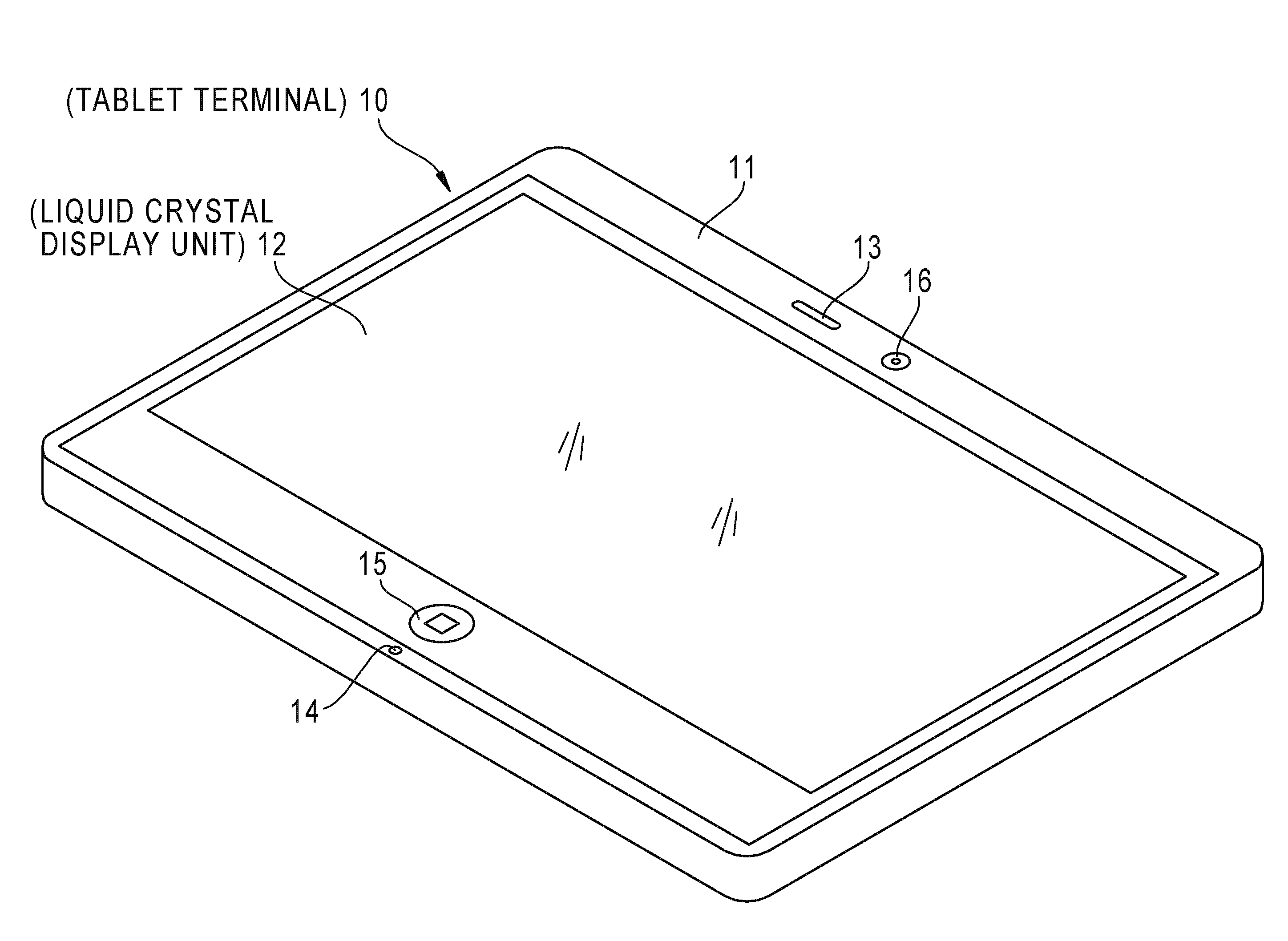
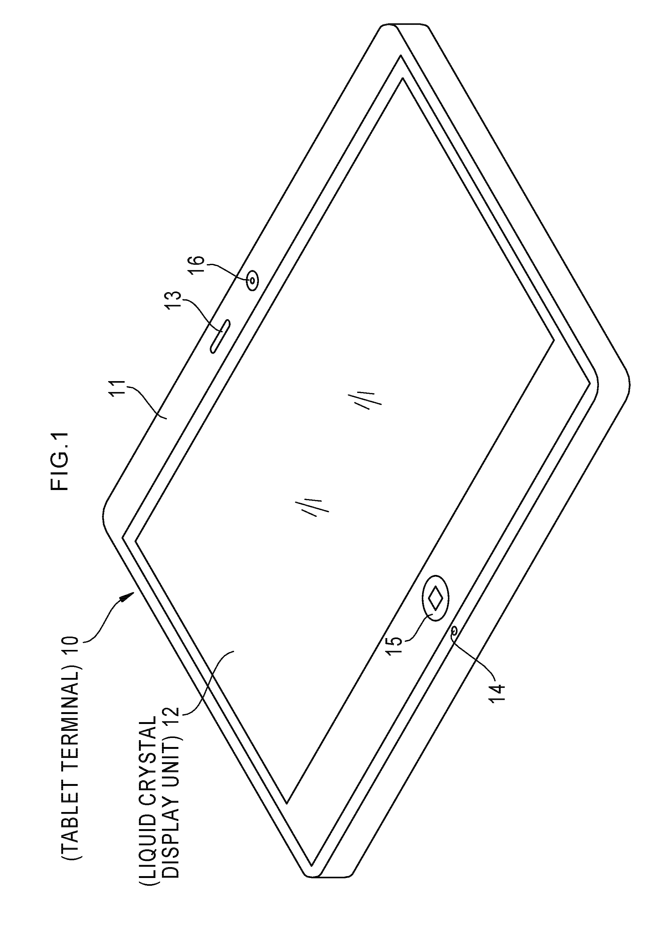
[0087]As shown in FIG. 1, a tablet terminal 10 corresponding to a liquid crystal display device of the present invention includes a tabular housing 11. The housing 11 is provided on one surface thereof with a liquid crystal display unit 12, a loudspeaker 13, a microphone 14, an operation unit 15, and a camera unit 16. A configuration of the housing 11 is not limited to the configuration described above, and a configuration in which the liquid crystal display unit, and various input units such as another operation unit are provided separately is also applicable.

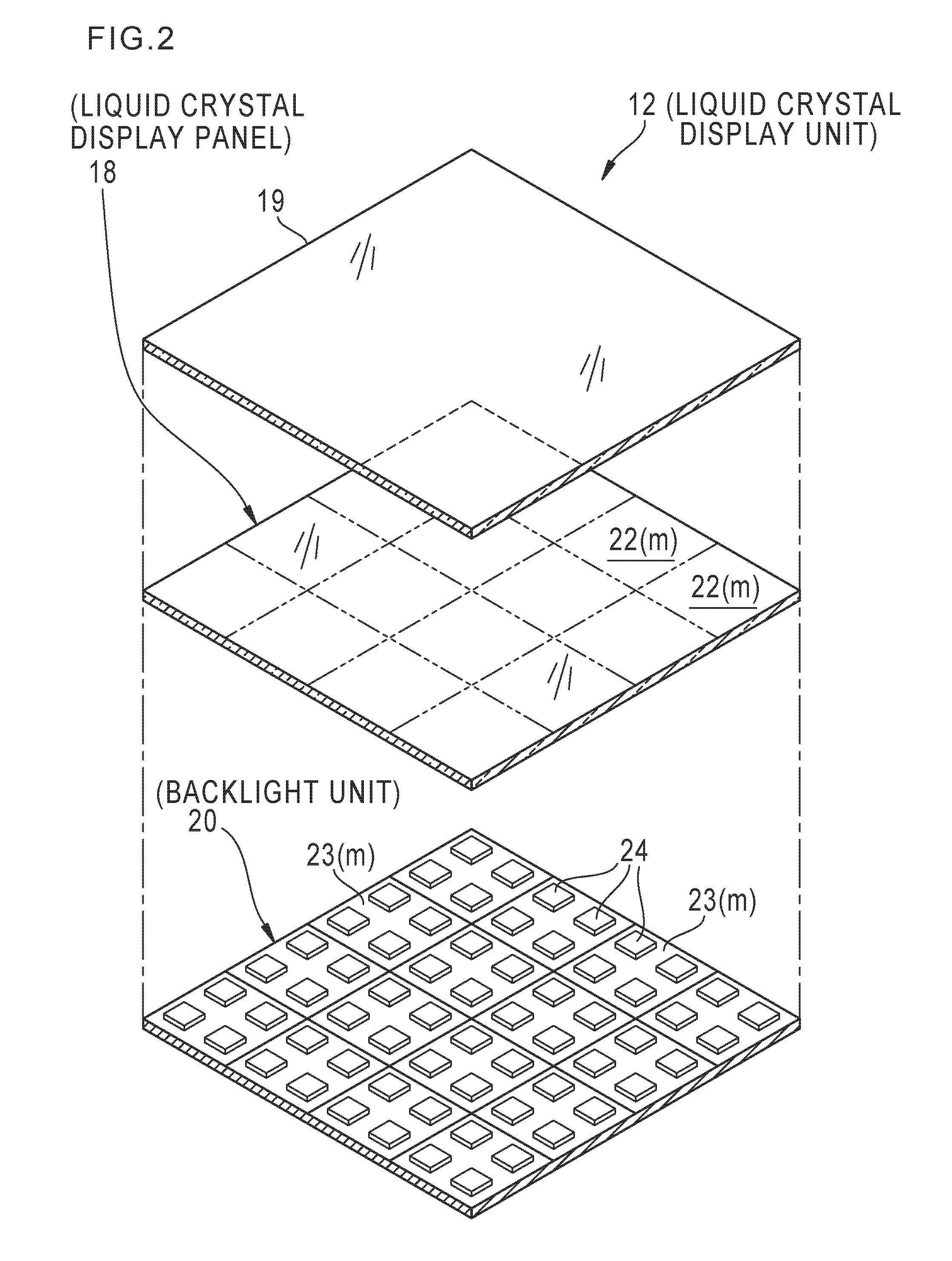
[0088]As shown in FIG. 2, the liquid crystal display unit 12 has a so-called touch panel structure in which an image (such as a still image and a moving image) and character information are displayed, as well as user's operation with respect to displayed information is detected. The liquid crystal display unit 12 is composed of a liquid crystal display panel (hereinafter, referred to as LCD pane...

second embodiment

Configuration of Tablet Terminal of Second Embodiment

[0163]Next, with reference to FIG. 12, a tablet terminal 60 of the second embodiment of the present invention will be described. In the first embodiment described above, although there has been described a case where a still image is displayed, the tablet terminal 60 has a function of displaying a moving image. The tablet terminal 60 has the essentially same configuration as that of the first embodiment except that the external storage unit 28b stores moving image data 63 previously acquired by the camera unit 16 and the wireless communication unit 25. Thus, a component having the same function and configuration as those of the first embodiment described above is designated by the same reference numeral as that of the first embodiment so that description of the component is appropriately omitted.

[0164]The image data acquisition unit 38 sequentially acquires (reads) each of frame image data sets 63a of the moving image data 63 sele...

third embodiment

Configuration of Tablet Terminal of Third Embodiment

[0179]Next, with reference to FIG. 16, a tablet terminal 66 of the third embodiment of the present invention will be described. In the second embodiment described above, when a moving image is displayed, each of the luminance set values L(m) is corrected for every frame image data 63a. Thus, there is a possibility that fluctuations of backlight luminance between frame images increase to cause a flicker to occur in a moving image. In addition, if each of the luminance set values L(m) is corrected for every frame image, a calculation load of the CPU 33 increased. Because of this, in the tablet terminal 66, each of the luminance set values L(m) is corrected for each of a plurality of frame groups FG into which the respective frame image data sets 63a of the moving image data 63 are divided (refer to FIG. 19).

[0180]The tablet terminal 66 has the essentially same configuration as that of the second embodiment except that the backlight l...


PUM


Abstract

A liquid crystal display device where the luminance control unit determines a coefficient KU, where KU<1, as the coefficient and repeatedly multiplies each of the luminance set values by the coefficient KU until the first integrated value is within the range of the first threshold value in a case where the first integrated value is larger than the range of the first threshold value, and the luminance control unit determines a coefficient KL, where KL>1, as the coefficient and repeatedly multiplies each of the luminance set values by the coefficient KL until the first integrated value is within the range of the first threshold value in a case where the first integrated value is smaller than the range of the first threshold value.

Description

CROSS-REFERENCE TO RELATED APPLICATIONS[0001]This application is a Continuation of PCT International Application No. PCT / JP2013 / 077771 filed on Oct. 11, 2013, which claims priority under 35 U.S.C. §119(a) to Japanese Patent Application No. 2013-31055 filed on Feb. 20, 2013. Each of the above application(s) is hereby expressly incorporated by reference, in its entirety, into the present application.BACKGROUND OF THE INVENTION[0002]1. Field of the Invention[0003]The present invention relates to a liquid crystal display device that performs backlight local dimming control.[0004]2. Description of the Related Art[0005]A liquid crystal display device is provided in a portable terminal such as a tablet terminal and a smartphone, a digital camera, a TV, and various monitors, in many cases. The liquid crystal display device includes a liquid crystal display panel in which liquid crystal elements with adjustable light transmittance are arranged to form a two-dimensional array, and a backlight...

Claims


Application Information

Patent Timeline
Patent Type & Authority Applications(United States)
IPC IPC(8): G09G3/20G09G3/36
CPCG09G3/2003G09G2320/0626G09G3/36G09G3/3426G09G3/3648G09G5/003G09G2300/023G09G2320/062G09G2320/0646G09G2360/16G02F1/133601
Inventor WATANABE, MIKIO
Owner FUJIFILM CORP
Why Eureka
Try Eureka