
Liquid crystal display device and method for driving liquid crystal display device

a liquid crystal display and display device technology, applied in the direction of electric digital data processing, instruments, computing, etc., can solve the problems of impairment of display quality, and decrease of expressive gradations, so as to curb response speed. high, the effect of reducing the deterioration of gradation expression ability

Inactive Publication Date: 2010-12-16
SHARP KK
View PDF28 Cites 5 Cited by
  • Summary
  • Abstract
  • Description
  • Claims
  • Application Information

AI Technical Summary

Benefits of technology

[0014]The present invention is achieved in view of the above problems, and an object thereof is to provide a technique for curbing a decrease in the response speed of the gradation shift to white display at a low temperature and maintaining the gradation expression ability in a liquid crystal display device displaying an image by using overshoot driving.
[0036]Furthermore, making the irradiation luminance of the backlight higher makes it possible to compensate for a decrease in luminance arising from the shift process of the gradation values that causes the upper gradation values to be unused.

Problems solved by technology

However, in the method described in above Patent Literature 1, the reduction of the dynamic range causes the number of expressive gradations to decrease.
This leads to problems of deterioration in gradation expression ability and an impairment of display quality.
Moreover, disregarding gradation values of the black side by not using the gradation values in a range from 0 to 15, for example, results in another problem that the black display becomes brighter and the contrast decreases.

Method used


Image

  • Liquid crystal display device and method for driving liquid crystal display device
  • Liquid crystal display device and method for driving liquid crystal display device
  • Liquid crystal display device and method for driving liquid crystal display device

Examples


Embodiment Construction

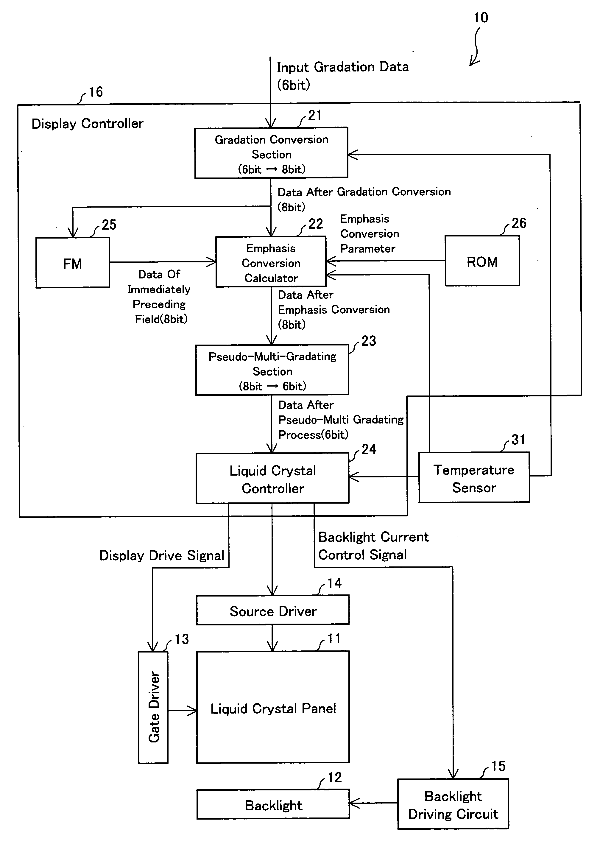
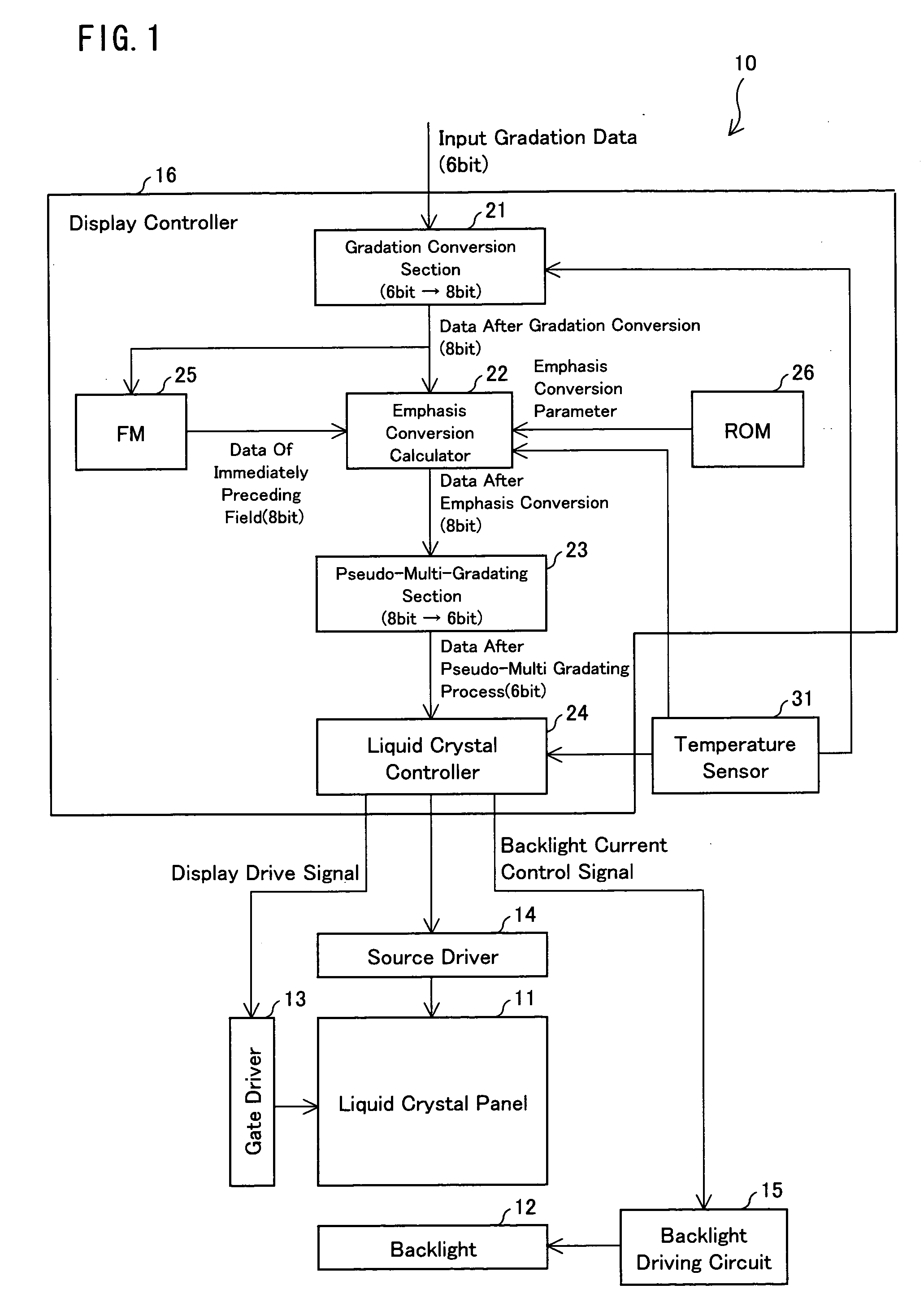
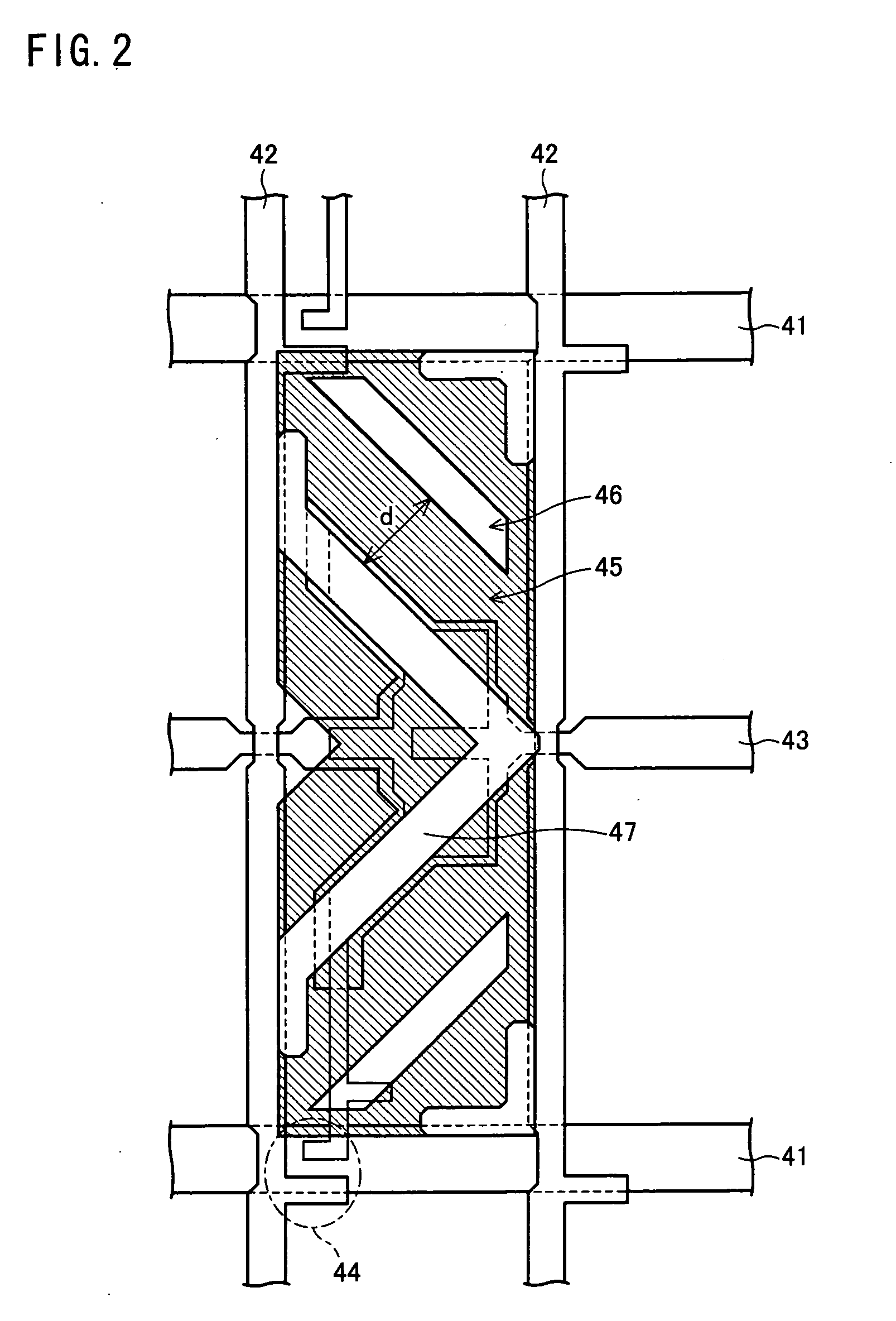
[0070]An embodiment of the present invention will now be described with reference to FIGS. 1 to 8. Note that the present invention is not limited thereto.

[0071]A liquid crystal display device according to the present embodiment performs displaying by using an overshoot driving. The overshoot driving is a display driving method for improving a response speed of liquid crystal. In the present embodiment, a liquid crystal display device, which includes a liquid crystal panel of a vertical alignment mode (VA mode) and polarizers disposed such that the liquid crystal display operates in a. normally black mode, is described by way of example.

[0072]In the present embodiment, an in-vehicle liquid crystal display device is also described by way of example. The in-vehicle liquid crystal display device is a device mounted in a vehicle for displaying information provided by various sensors and in-vehicle equipments. The in-vehicle liquid crystal device can also be used as a car navigation syste...


PUM


Abstract

A liquid crystal display device displays an image by using overshoot driving. In at least one embodiment, the liquid crystal display device includes: a temperature sensor measuring a surface temperature of a liquid crystal panel; a gradation conversion section performing a gradation value shift process of shifting inputted gradation values to lower gradation values; and a pseudo-multi-gradating section performing a pseudo-multi-gradating process on image data on which the gradation value shift process has been performed by the gradation conversion section. The gradation conversion section decides whether or not to perform the gradation value shift process depending on the surface temperature of the liquid crystal panel measured by the temperature sensor.

Description

TECHNICAL FIELD [0001]The present invention relates to a liquid crystal display device in which response speed of liquid crystal is improved by performing an overshoot drive, and to a method for driving the liquid crystal display device.BACKGROUND ART [0002]In recent years, liquid crystal display devices (LCD) have come to be widely used as image display devices for PCs and TVs and are replacing image display devices of cathode ray tube (CRT) type. The LCDs are display devices configured by injecting, between two substrates, a liquid crystal layer having anisotropic permittivity. Adjusting strength of the electric field applied to the liquid crystal layer allows an amount of light passing through the substrates to be adjusted. As a result, a desired image signal is obtained.[0003]Various studies are currently being made to improve performance of the LCDs. One of such studies is concerned with improvement of a response speed of the liquid crystal. In order to increase the response sp...

Claims


Application Information

Patent Timeline
Patent Type & Authority Applications(United States)
IPC IPC(8): G09G5/10G09G3/36
CPCG09G3/3648G09G2320/0252G09G2320/0271G09G2320/041G09G2340/16G02F1/133707G02F2203/30G02F2203/60
Inventor FURUKAWA, TOMOOFUJIOKA, KAZUYOSHI
Owner SHARP KK
Learn More