
Automatic uncoupling mechanism for couplers

a technology of uncoupling mechanism and coupler, which is applied in the direction of railway couplings, railway coupling accessories, railway components, etc., can solve the problems of damage to the paint on the coupler knuckle, difficult maintenance, and low response speed. , the effect of poor stability

Active Publication Date: 2019-05-16
CRRC QINGDAO SIFANG ROLLING STOCK RES INST
View PDF0 Cites 2 Cited by
  • Summary
  • Abstract
  • Description
  • Claims
  • Application Information

AI Technical Summary

Benefits of technology

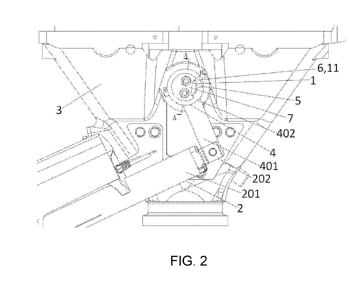
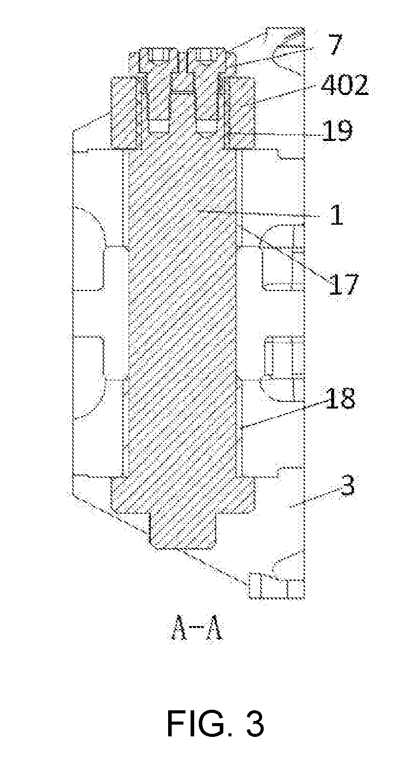
The present patent application improves the automatic coupling device for couplers by adding a first rotating member, boss, and boss stopper, and configuring a split-type connection relationship between the first rotating member and the coupler knuckle spindle. This allows for independent rotation of the coupler knuckle spindle during both the uncoupling and coupling processes, ensuring efficient and reliable coupling. Additionally, the application combines the split-type connection approach with the electric uncoupling approach, improving the stability and efficiency of the automatic uncoupling device for couplers, and ensuring smooth implementation of the couplers coupling process.

Problems solved by technology

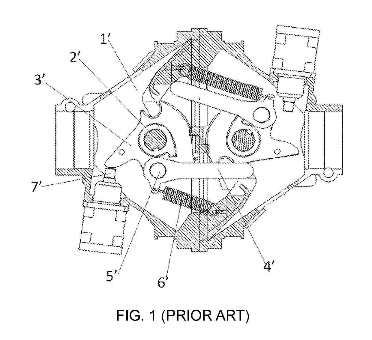
However, since the surface of the coupler knuckle 3′ coming into contact with the uncoupling piston rod 7′ is relatively short, it is very difficult to ensure that the stress direction of the coupler knuckle 3′ is always along the direction of the piston rod 7′.
As a result, there will be some problems, such as the coupler knuckle 3′ applying a large lateral force to the cylinder piston rod 7′ and the cylinder piston rod 7′ causing damage to the paint on the coupler knuckle.
However, this uncoupling device still has the following technical problems.
After the couplers are rotated to a maximum angle, due to the resistance from the cylinder rod, the coupler knuckles are difficult to quickly rotate and lock the two couplers under the tension of the tension springs.
However, in this uncoupling device, the resistance generated when the tension spring pulls the coupler knuckle to return to its position is not completely eliminated, so during the coupler coupling process, the coupler knuckle is still very difficult to quickly rotate and lock two couplers under the tension of the tension spring.

Method used


Image

  • Automatic uncoupling mechanism for couplers
  • Automatic uncoupling mechanism for couplers
  • Automatic uncoupling mechanism for couplers

Examples


Embodiment Construction

[0047]In the following, the present application is specifically described by way of exemplary embodiments. However, it should be understood that elements, structures, and features of an embodiment may be beneficially incorporated into other embodiments without further recitation.

[0048]In the description of the present application, it should be noted that the terms “inside”, “outside”, “up”, “down”, “front”, “back”, “left”, “right”, “clockwise”, “anticlockwise” and the like indicate the positional or positional relationship according to the positional relationship shown in the drawings merely for the convenience of describing the present application and the simplified description, but do not indicate or imply a devices or an element referred to must be of a particular orientation, constructed and operated in a particular orientation and therefore should not be construed as limiting the present application. Moreover, the terms “first”, “second”, “third” and the like are used merely fo...


PUM


Abstract

An automatic uncoupling mechanism for couplers comprises a coupler knuckle spindle and a driving unit comprising a cylinder body hinged to a coupler body and a telescopic member; and further comprises a first rotating member, a boss and a boss stopper, wherein the first rotating member comprises a crank hinged to the telescopic member and a rotating part being sheathed on the coupler knuckle spindle. The driving unit unidirectionally drives the telescopic member so that the rotating part drives the coupler knuckle spindle to unidirectionally rotate by the contact of the boss with the boss stopper, realizing coupler uncoupling; and, after the driving unit drives the telescopic member to return to its position, the rotation of the coupler knuckle spindle for achieving coupler coupling is not limited by the rotating part. The present application may reduce the lateral force of the coupler knuckle to the driving unit during the uncoupling process of the coupler, and may cause the spring to drive the coupler knuckle to rotate rapidly and lock the coupler during the coupler coupling process.

Description

CROSS-REFERENCE TO RELATED APPLICATION[0001]This application is a continuation of International Application No. PCT / CN2017 / 097009 filed on Aug. 11, 2017, which in turn claims the priority benefits of Chinese application No. 201610778788.8 filed on Aug. 31, 2016. The contents of these prior applications are hereby incorporated by reference in its entirety.TECHNICAL FIELD[0002]The present application belongs to the technical field of coupling devices for train couplers and particularly relates to an automatic uncoupling mechanism for couplers.BACKGROUND OF THE PRESENT INVENTION[0003]As the basic composition of a coupling device for couplers, an uncoupling device functions to push a coupler knuckle mechanism to rotate so as to uncouple couplers. Prior uncoupling methods include manual uncoupling and automatic uncoupling, wherein the prior automatic uncoupling method for railway vehicles in China is pneumatic uncoupling. A conventional uncoupling device is shown in FIG. 1. Two uncouplin...

Claims


Application Information

Patent Timeline
Patent Type & Authority Applications(United States)
IPC IPC(8): B61G7/00
CPCB61G7/00B61G3/14B61G3/20B61G7/02
Inventor LIU, QUANDU, JINTAOLI, MINGGANGLIU, JIBO
Owner CRRC QINGDAO SIFANG ROLLING STOCK RES INST
Learn More