
Flash illumination device for use with electronic apparatus or mobile device

a technology of flash illumination and electronic equipment, which is applied in the direction of electric lighting with batteries, lighting and heating apparatus, instruments, etc., can solve the problems of consuming a certain amount of electrical power, taking pictures with flashes, and a large amount of light-emitting diodes which serve as flashes, etc., and achieves low response speed, high degree of flexible bendability, and high response speed

Active Publication Date: 2016-11-24
CHANG
View PDF0 Cites 1 Cited by
  • Summary
  • Abstract
  • Description
  • Claims
  • Application Information

AI Technical Summary

Benefits of technology

This patent describes a flash illumination device for electronic devices and mobile devices. The device is designed to be low-power, surface-emitting, and can provide instantaneous or persistent light for supplemental lighting during video capture. It is controlled by the electronic device and operates quickly and efficiently. Compared to traditional flash devices, this organic light-emitting diode (OLED) technology is much faster, energy-efficient, and flexible, overcoming limitations of prior art. In summary, this patent presents a new flash device that improves the quality and performance of electronic devices and mobile devices.

Problems solved by technology

The camera lens of each early mobile phone does not come with a flash; as a result, pictures taken with early mobile phones in a dim environment are seldom clear.
Taking pictures with a flash is confronted with a problem, that is, the light-emitting diode which serves as the flash consumes a certain amount of electrical power otherwise available to the mobile phone.
Hence, a conventional light-emitting diode which serves as a flash is likely to use up all the electrical power of the mobile phone after several instances of operation.
In addition, light is emitted from a light-emitting diode instantaneously and in a point-emitting manner; as a result, the light emitted from a light-emitting diode is not only unfit for supplemental lighting but also occurs only at the instant of flashing.
Furthermore, LED light-emitting diodes differ from sunlight in color temperature and color spectrum, and thus the light emitted from light-emitting diodes are greatly distorted and unnatural even if it were conducive to supplemental lighting.
As a result, not only must light-emitting diodes be mounted on something thick to thereby garner more weight and thickness, but light-emitting diodes also require an intricate manufacturing process and assembly process and thus incur much manufacturing costs; in view of this, light-emitting diodes are not the best source of light.
As time goes by, the Earth is going to run out of natural resources.
Also, a single light-emitting diode disposed at the mobile phone is obviously not bright enough to provide optimal illumination and broad illumination.
Furthermore, the point-emission of a light-emitting diode is too strong to be seen directly with the naked eye, otherwise the watchers will not only have their pupil contracted instantly to thereby perceive dark images and residual images but also suffer eventually from poor accommodation of lens or retinopathy, thereby ending up with visual impairment.
Evidently, attempting to imitate the natural light source, light-emitting diodes do not provide the best solution to human beings' demand for illumination, not to mention that the blue light emitted from light-emitting diodes is harmful to the human eyes.

Method used


Image

  • Flash illumination device for use with electronic apparatus or mobile device
  • Flash illumination device for use with electronic apparatus or mobile device
  • Flash illumination device for use with electronic apparatus or mobile device

Examples


Embodiment Construction

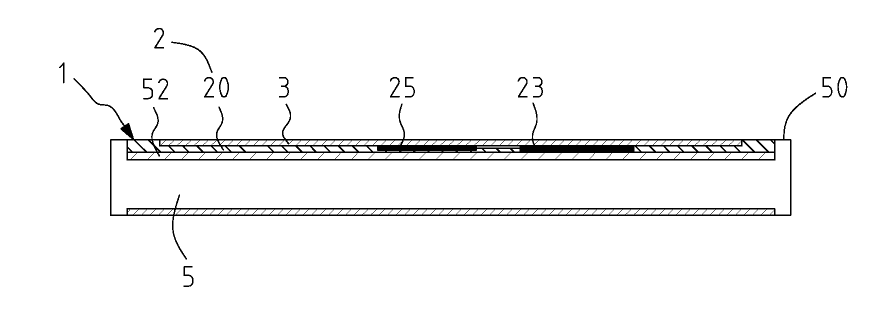
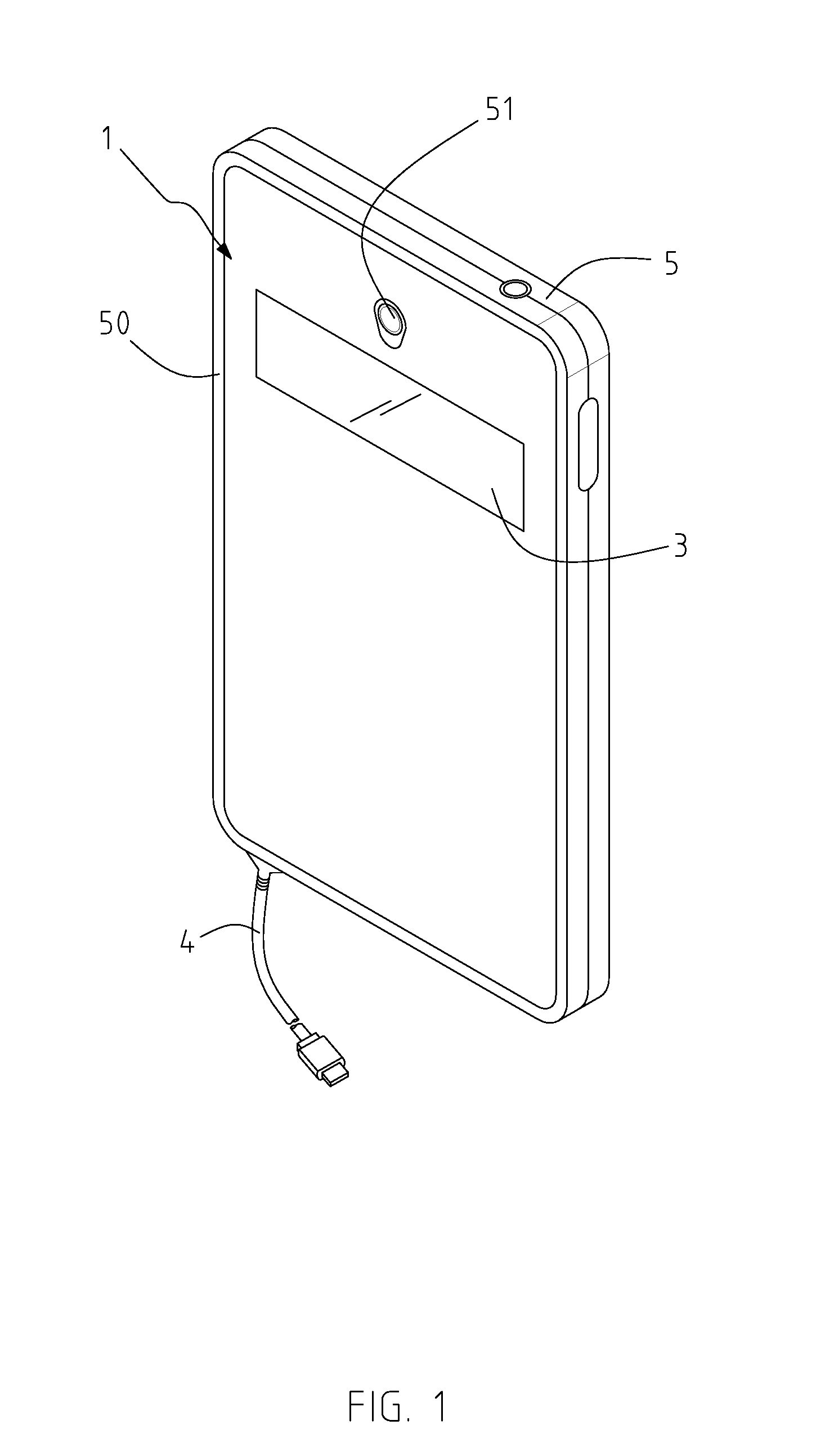
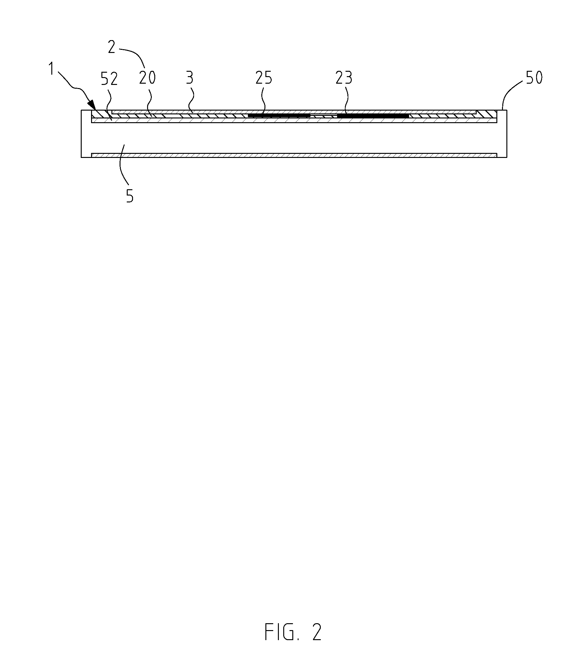
[0022]Referring to FIG. 1 through FIG. 3, there are shown diagrams of the first preferred embodiment of the present invention. The present invention provides a flash illumination device 1 for use with an electronic apparatus 5 or a mobile device. The electronic apparatus 5 is a smartphone or a tablet. The electronic apparatus 5 is built in with a display screen (not shown) and a video shooting component 51 which has a lens for use in taking pictures and shooting videos. The primary objective of the flash illumination device 1 of the present invention is to function as a flash for emitting instantaneous or persistent light while picture taking or video shooting is underway so as to provide supplemental lighting.

[0023]According to the present invention, the flash illumination device 1 for use with an electronic apparatus comprises a connection unit 2 and at least one organic light-emitting diode (OLED) unit 3. The organic light-emitting diode unit 3 is coated on a lateral surface of t...


PUM


Abstract

A flash illumination device for use with an electronic apparatus is provided and includes a connection unit and at least one organic light-emitting diode unit. The electronic apparatus includes a video shooting component or a display screen. The connection unit electrically connects with the electronic apparatus. The organic light-emitting diode unit is coated on a lateral surface of the connection unit and electrically connected to the electronic apparatus through the connection unit. The organic light-emitting diode unit starts under the control of the electronic apparatus and emits instantaneous light or persistent light, which is conductive to low power consumption and characterized by surface emission, while the video shooting component is capturing an image, so as to provide supplemental lighting.

Description

BACKGROUND OF THE INVENTION[0001]1. Field of the Invention[0002]The present invention relates to illumination devices, and more particularly, to a flash illumination device for use with mobile related electronic products to provide illumination which simulates natural light in order to be acceptable to the human eyes. The flash illumination device is energy-efficient, compact, flexible, diverse in shape, and capable of surface emission typical of an organic light-emitting diode.[0003]2. Related Art[0004]Mobile electronic products evolve by leaps and bounds, from desktop personal computer, notebooks, digital cameras, tablet pad computers, to smartphones, providing ever-changing functions. Mobile electronic products not only provide wireless communication but are also capable of taking pictures and shooting videos. The emergence of social networking websites and social networking applications brings about a phenomenon, that is, most mobile electronic product users can take pictures an...

Claims


Application Information

Patent Timeline
Patent Type & Authority Applications(United States)
IPC IPC(8): G03B15/05H01L51/50F21V23/02F21V23/04F21L4/02F21L4/08
CPCG03B15/05F21L4/02F21L4/08F21Y2101/02F21V23/0414F21V23/045H01L51/504F21V23/023G03B2215/0567H04M1/185H04M1/22H04N23/56H04N23/00H10K50/13F21Y2101/00
Inventor CHANG
Owner CHANG
Learn More