Image display apparatus
a technology of image display and backlight luminance, which is applied in the direction of instruments, computing, electric digital data processing, etc., can solve the problems of deteriorating image quality, affecting the image quality, and the control of backlight luminance may not cope with the video image having the display image luminance, so as to suppress the deterioration of image quality and reduce the power consumption of backligh
- Summary
- Abstract
- Description
- Claims
- Application Information
AI Technical Summary
Benefits of technology
Problems solved by technology
Method used
Image
Examples
first embodiment
[First Embodiment]
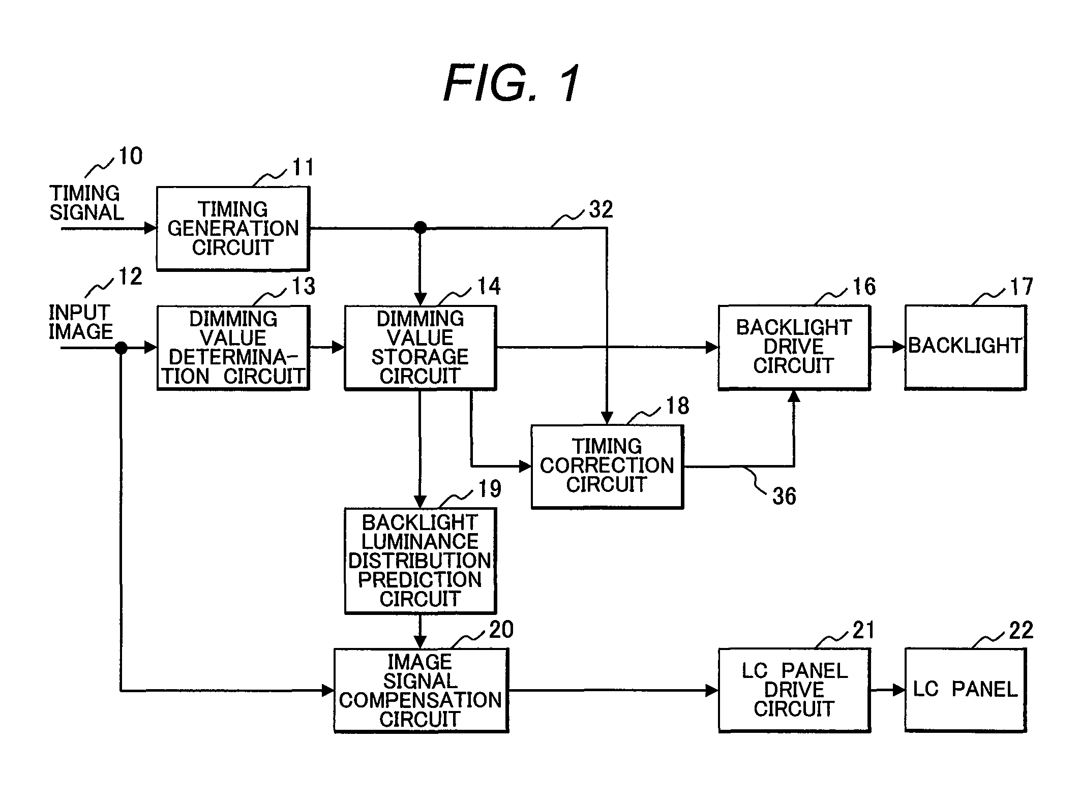
[0058]FIG. 1 is a block diagram illustrating an image display apparatus according to a first embodiment of the present invention.
[0059]An input image 12 to be displayed and a timing signal 10 indicating timing information of the input image 12 are input to the apparatus. Dot clocks and synchronous signals correspond to the timing signal 10. A timing generation circuit 11 generates various timing signals such as clock, address, and trigger signal based on the input timing signal 10 so as to be supplied to the respective circuits in the apparatus. Those timing signals are only partially described for avoiding the complexity drawing.
[0060]A dimming value determination circuit 13 analyzes the input image 12 which has been input, and determines a light emission amount (hereinafter referred to as a dimming value) of each of the light sources for forming a backlight 17. The light emission amount of the light source is determined based on the pixel value with the maximum l...
second embodiment
[Second Embodiment]
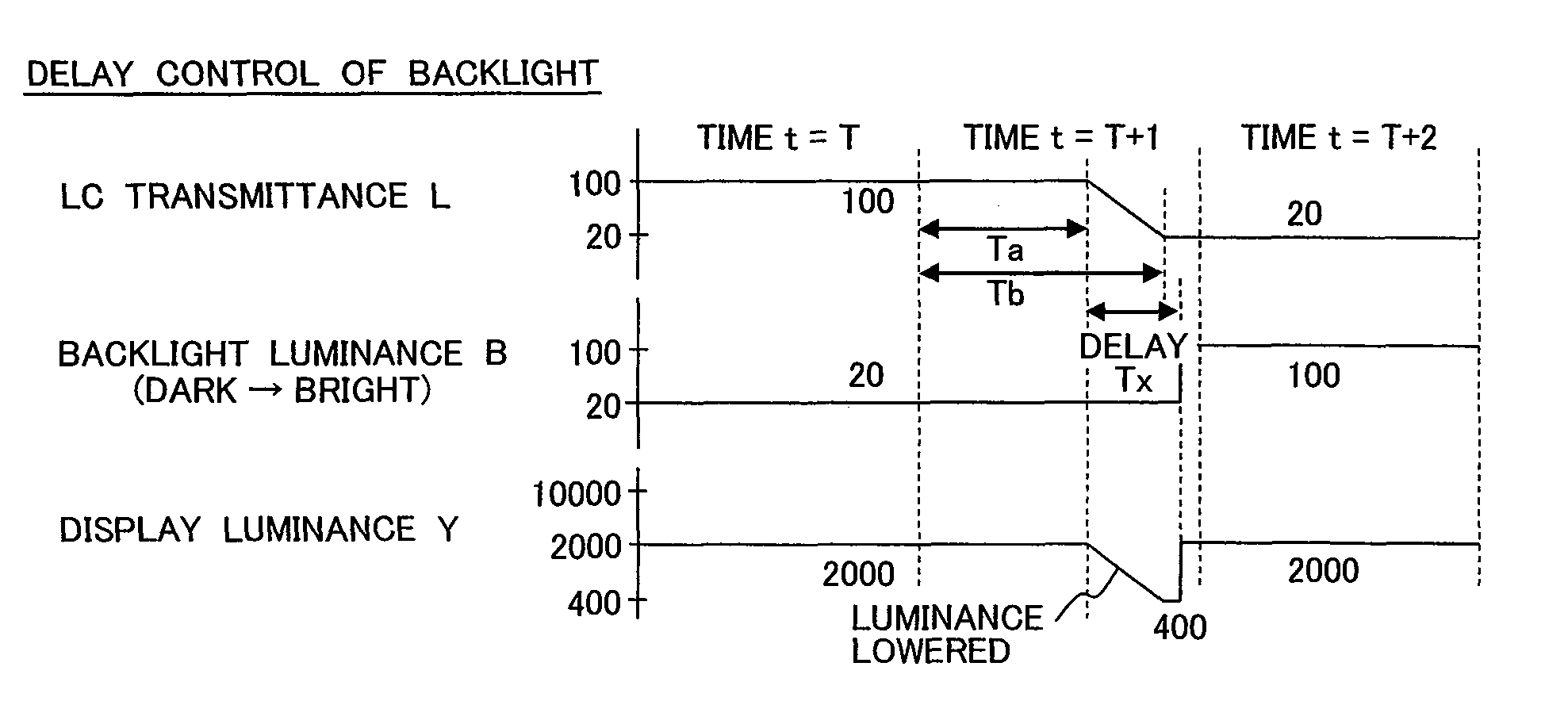
[0094]In a second embodiment, the value of the delay time Tx is fixed to the time corresponding to the single frame. In this case, the backlight luminance (dimming value) of the previous frame may be continuously used for the present frame to establish the delay time Tx for the single frame so as to omit the delay circuit.
[0095]FIG. 8 is a block diagram representing the image display apparatus according to the second embodiment of the present invention. Referring to the drawing, a dimming value change determination circuit 40 determines with respect to the trend of change in the dimming value along the time axis for each region. A dimming value selection circuit 41 selects the dimming value to be used based on the determination result from the dimming value change determination circuit 40. Structures of other circuits are the same as those described in the first embodiment (FIG. 1).
[0096]FIG. 9 illustrates an example of inner structures of the dimming value change...
third embodiment
[Third Embodiment]
[0099]In a third embodiment, the backlight luminance (dimming value) is changed by setting an intermediate level without changing at a time. That is, in the single frame period at the switching point, the intermediate value (correction value) obtained from the backlight luminance values before / after the switching is set to reduce fluctuation of the display luminance.
[0100]FIG. 11 is a block diagram illustrating an image display apparatus according to a third embodiment of the present invention. Referring to the drawing, a dimming value change determination circuit 50 determines a change amount of the dimming value for each region, and outputs correction coefficients C and (1−C). A dimming value correction circuit 51 uses the correction coefficients C and (1−C) to determine the correction value. Structures of the other circuits are the same as those described in the first embodiment (FIG. 1).
[0101]FIG. 12 illustrates an example of inner structures of the dimming val...
PUM
| Property | Measurement | Unit |
|---|---|---|
| light transmittance | aaaaa | aaaaa |
| light emitting luminance | aaaaa | aaaaa |
| transmittance | aaaaa | aaaaa |
Abstract
Description
Claims
Application Information
 - R&D
- Intellectual Property
- Life Sciences
- Materials
- Tech Scout
- Unparalleled Data Quality
- Higher Quality Content
- 60% Fewer Hallucinations
Browse by: Latest US Patents, China's latest patents, Technical Efficacy Thesaurus, Application Domain, Technology Topic, Popular Technical Reports.
© 2025 PatSnap. All rights reserved.Legal|Privacy policy|Modern Slavery Act Transparency Statement|Sitemap|About US| Contact US: help@patsnap.com


