Motor driving system

a technology of motor driving and driving system, which is applied in the direction of electronic commutation motor control, electric controller, association with control/drive circuit, etc., can solve the problems of troublesome and complex configuration of the motor driving system, and achieve the effect of simplifying the configuration and simplifying the configuration

Active Publication Date: 2016-03-08
NIDEC SERVO CORP
View PDF8 Cites 0 Cited by
  • Summary
  • Abstract
  • Description
  • Claims
  • Application Information

AI Technical Summary

Benefits of technology

[0009]Preferred embodiments of the present invention provide a simplified configuration of an input device associated with a speed control interface as compared with the conventional devices.
[0012]With a preferred embodiment of the present invention, the input device arranged to input the speed command can be configured to merely comply with relaxed safety standards without having to satisfy the safety standards on a commercial power supply. This makes it possible to simplify the configuration as compared with the conventional configuration.
[0013]In the motor driving system according to a preferred embodiment of the present invention, the signal insulating unit may include a photo coupler. This makes it possible to transmit the speed command over a wide enough frequency band and to use the signal insulating unit in transmitting different types of speed commands. The speed command may be a pulse width modulation signal, and a pulse width of the pulse width modulation signal is changed depending on the speed command. This makes it possible to further simplify the configuration as compared with the conventional configuration.
[0014]The input device may include a reference signal generating circuit configured to generate a reference signal used as a reference in generation of the pulse width modulation signal and a first comparator circuit configured to generate the pulse width modulation signal by comparing a speed command voltage indicating a rotation speed with the reference signal and outputting the result of comparison. The reference signal may be a charge-discharge waveform signal whose signal level is changed at a specified frequency. The signal level may be changed more sharply at a rising time than at a falling time. This makes it possible to generate the pulse width modulation signal by maintaining the timing of one of a rising edge and a falling edge substantially constant and by changing the timing of the other of the rising edge and the falling edge.
[0015]The reference signal generating circuit may be configured to generate the reference signal by controlling a charge and discharge of a capacitor depending on an output of a second comparator circuit to which a terminal voltage of the capacitor is inputted. The input device may be configured to generate a speed command voltage by dividing the power supply voltage of the second comparator circuit. This makes it possible to generate the pulse width modulation signal without being affected by the fluctuations of a power supply voltage.

Problems solved by technology

As a result, there is a problem in that the configuration of the motor driving system becomes complex and troublesome.

Method used


Image

  • Motor driving system
  • Motor driving system
  • Motor driving system

Examples


first preferred embodiment

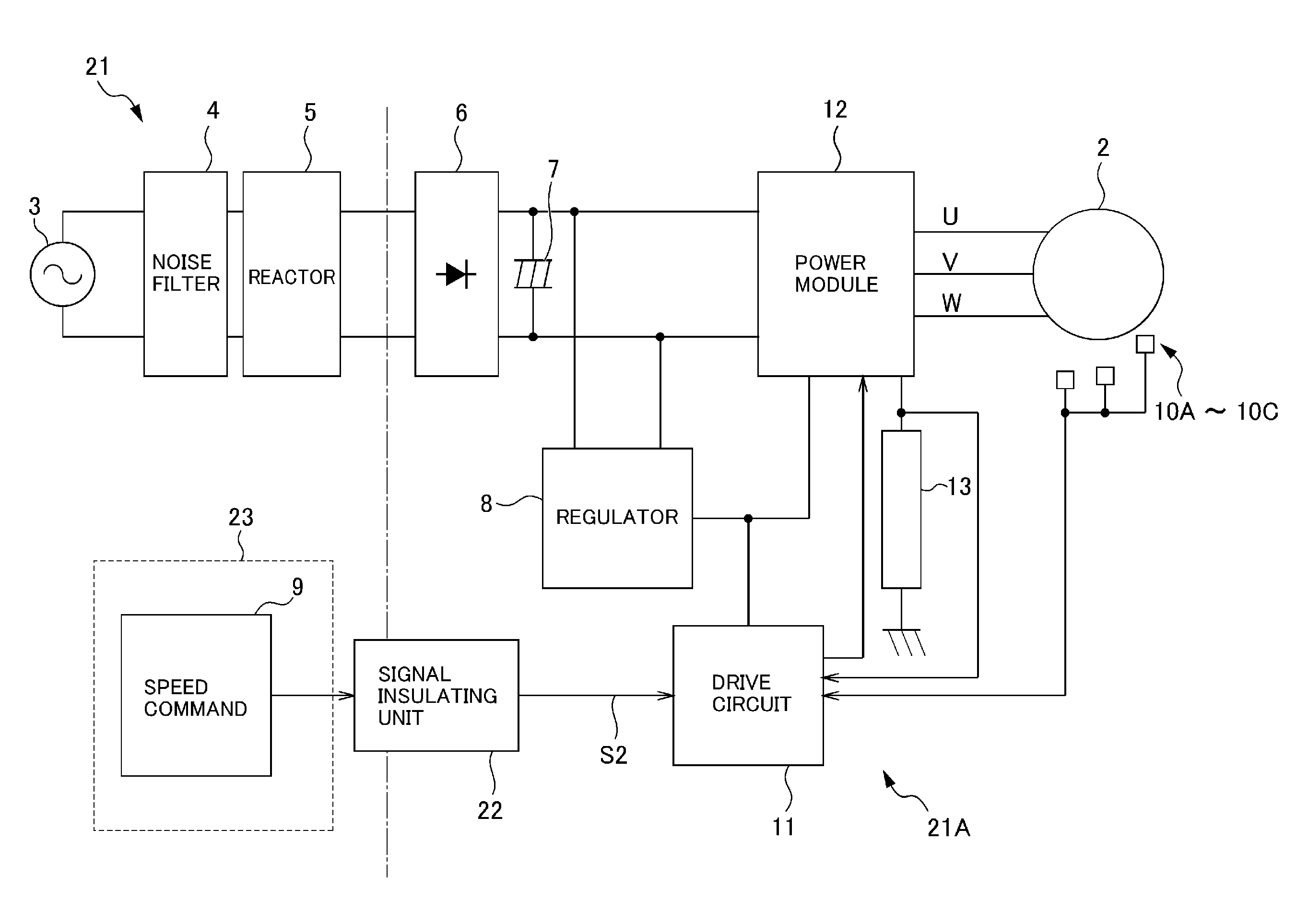
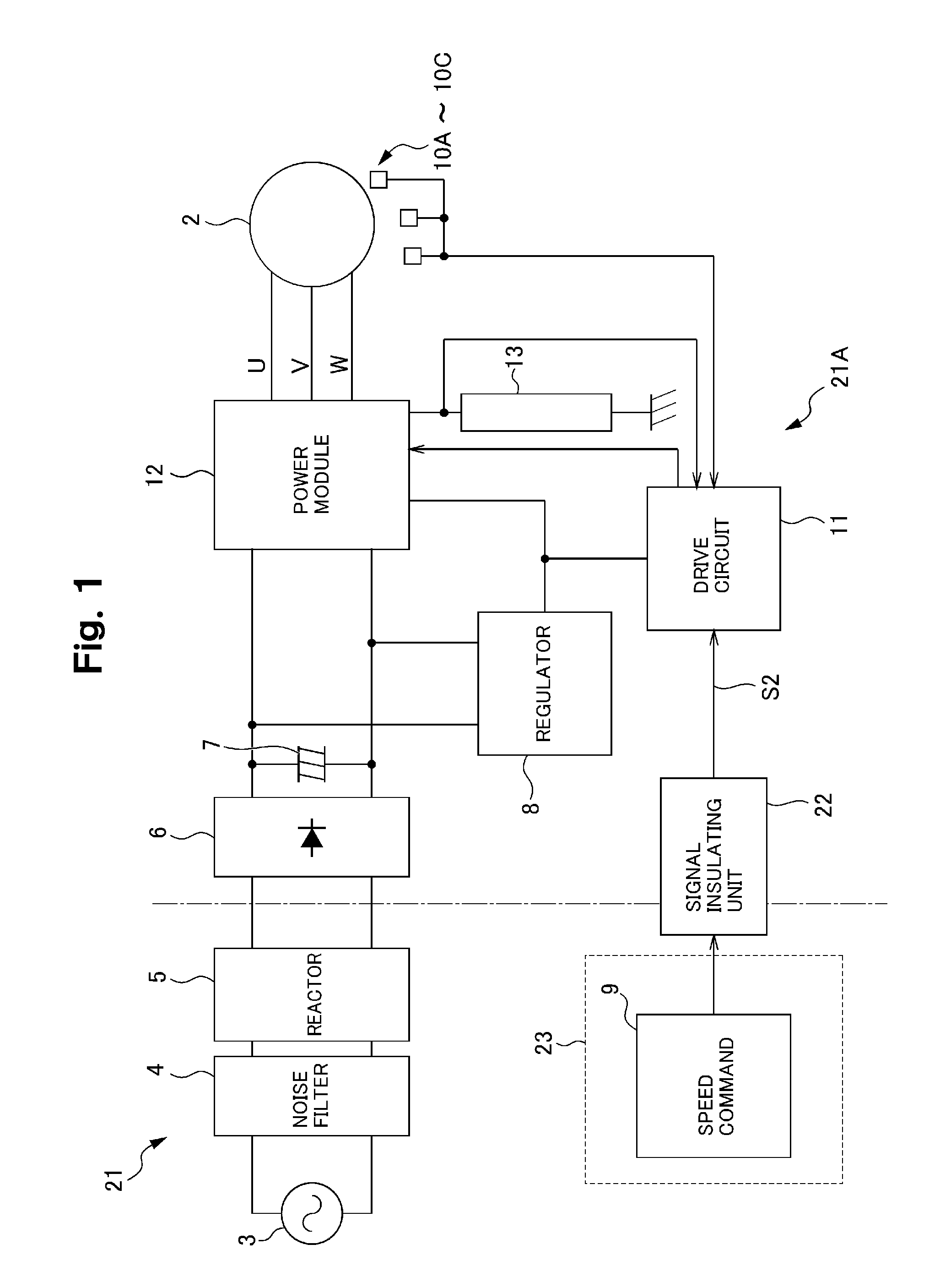
[0024]FIG. 1 is a block diagram showing a motor driving system according to a first preferred embodiment of the present invention, which is compared with FIG. 6 described above. The motor driving system 21 includes a main device 21A and an input device 23. The main device 21A preferably includes a drive circuit 11, a power module 12, a current detecting element 13, a rectifying circuit 6, a smoothing capacitor 7, and a regulator 8. The drive circuit 11 is configured to drive a fan motor 2. In this motor driving system 21, a signal insulating unit 22 is preferably provided at a position between the input device 23 and the drive circuit 11. In other words, the signal insulating unit 23 is configured to insulate the input device 23 from the main device 21A. The input device 23 is preferably operated by a power supply of Class II (Class II refers to power supplies with either a double or reinforced insulation barrier between the input and the output.), e.g., a battery, and is provided w...


PUM


Abstract

A motor driving system that changes a rotation speed of a motor pursuant to a speed command includes a main device including a drive circuit configured to drive the motor, an input device configured to input the speed command to the drive circuit, and a signal insulating unit configured to insulate the input device from the main device and to transmit the speed command from the input device to the drive circuit of the main device.

Description

BACKGROUND OF THE INVENTION[0001]1. Field of the Invention[0002]The present invention relates to a motor driving system configured to drive a motor such as a fan motor that forcibly circulates cold air in a freezing showcase or a refrigerator.[0003]2. Description of the Related Art[0004]In a fan motor for forcibly circulating cold air in a freezing showcase or a refrigerator, it is conventionally required to keep a rotation speed constant, to change over a rotation speed depending on the in-refrigerator situation, or to change a rotation speed pursuant to a predetermined program. The control of a rotation speed is performed by a motor driving system. From the viewpoint of electric power saving and ease of control, a brushless motor is often used as a motor to be driven by the motor driving system of this kind. In this case, some components of the motor driving system such as a rectifying circuit and a drive circuit for supplying an electric current to the brushless motor are arrange...

Claims


Application Information

Patent Timeline
Patent Type & Authority Patents(United States)
IPC IPC(8): G05B11/28H02P6/08H02K11/00H02P6/00H02P6/06H02P29/00
CPCH02K11/22H02K11/33H02P6/34H02P6/08
Inventor SILITONGA, CHARLES SIMSON HALASONOKABE, TOSHIHIROSOMA, AKIKOYAJIMA, MAKOTO
Owner NIDEC SERVO CORP
Why Eureka
Try Eureka